
How to Design Hot Forging Dies: Flash, Steel and Die Life
Table of Contents
A 12,000 USD set of H13 finisher dies can be scrap at 2,000 parts. The usual chain: a flash land cut too thin, a die sent to the press cold, an impression that washes out. Heat checking at 0.1 to 0.3 mm depth then arrives within 1,000 to 3,000 strikes, and short-fill defects follow inside a week. A replacement block costs 4 to 6 weeks plus a re-qualification trial. Hot forging die design is the control point between a tool that lives 2,000 parts and one that lives 20,000.
The route below walks the numbers for impression and trim tooling on hammers, presses and multistation lines. It reads the same whether you commission the dies or design them in house.
The Snapshot
- Flash land 0.4 to 1.5 mm on a 3 to 15 mm web. A land thinner than 0.4 mm washes out and heat-checks inside 3,000 strikes, because a thin H13 wall carries the full 5 to 25 percent flash force of the upset.
- Draft 3 to 7 degrees external, 5 to 10 degrees internal. Under 3 degrees, a 1,100 °C C-Mn part grabs the impression walls and scours 0.05 to 0.10 mm per 1,000 parts off the rib faces.
- H13 at 44 to 52 HRC, preheat 200 to 350 °C. A cold die chills the flash skin in the first seconds of contact. Thermal fatigue cracking then starts thousands of cycles early.
- Die life 5,000 to 15,000 strikes on aluminum, 10,000 to 40,000 on steel. Rebuild returns a block for another 5,000 to 10,000 strikes at 20 to 35 percent of block cost, with a CMM survey every 20,000 strikes.
The Hot Forging Process Family
Three process families share the word forging, and each defines a different die. Open-die forging squeezes a billet between flat tools with no cavity and no flash, so the tooling decision is trivial. Close-die impression forging with flash is the volume route, and every rule in this guide belongs to it.
Flashless or web-less forging on screw and multistation presses keeps metal inside a closed cavity. It kills the trim die and tightens tolerances by 30 to 50 percent, but the machine carries the burden. A 1 to 5 kg bracket or shaft defaults to the flash route.
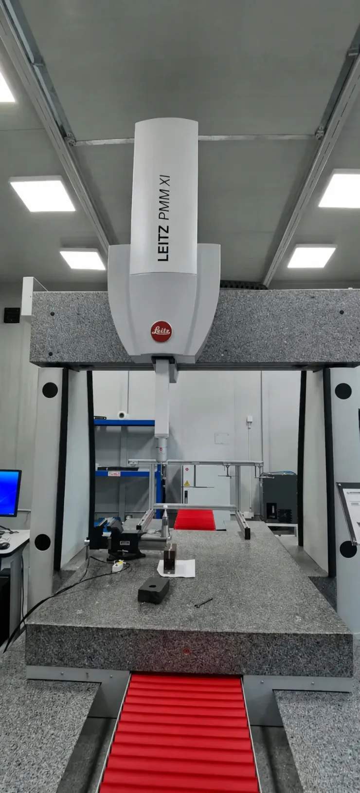
Equipment decides the strain rate, and strain rate decides impression design. A 40 to 160 kJ hammer works in 2 to 15 blows per part. High strain rate lets the forger push metal toward the flash edge. A 630 to 2,500 t friction or crank press closes in a squeeze and demands exact billet volume. Multistation lines in the 800 to 5,000 t class make crankshafts and connecting rods, with a die set at each station.
Temperature sets the metal side of the design. C-Mn and alloy steels forge between 950 and 1,200 °C, finishing above 800 °C. Aluminum alloys such as 6xxx run warm at 380 to 480 °C, and titanium near 900 to 950 °C. Preheat, coat, hardness and life all scale from that band.
Fix the equipment route in the RFQ before the die shop quotes. The same part print can run on a hammer, a press or a line, and die geometry, tolerances and life promises differ between them. Check cavity area and flash land against the press datasheet.
| Route | Machine class | Strain rate | Flash | Tolerance band |
|---|---|---|---|---|
| Open-die forging | 4,000 to 80,000 t hydraulic press | Low, 0.1 to 10 per s | None | +/-1 to 3 mm |
| Hammer impression | 40 to 160 kJ air or diesel hammer | High, 10 to 100 per s | Yes, land 0.4 to 1.5 mm | +/-0.3 to 0.7 mm |
| Press impression | 630 to 2,500 t friction or crank | Medium, 1 to 20 per s | Yes, volume-sensitive | +/-0.2 to 0.5 mm |
| Multistation flashless | 800 to 5,000 t line | High, closed cavity | None or web | +/-0.1 to 0.3 mm |
← swipe to scroll →
Table note: machine classes, strain rates and tolerance bands are typical industry ranges for steel and aluminum impression forging. Confirm the route, blow count and shut height against the forger's press datasheet before the die design is frozen.
Flash as a Design Element
In close-die impression forging, flash is a metering valve, not scrap sloppiness. The gutter gap is sized so the billet fills the impression before flash escapes. The thin web then freezes and locks pressure inside the cavity. Right geometry fills the corners at 800 to 900 °C core temperature. Wrong geometry pays in short fill, cold shuts and die wear.
Land thickness runs 0.4 to 1.5 mm on steel forgings and 0.4 to 1.0 mm on aluminum. Size it near 0.02 to 0.03 mm per square millimeter of projected cavity area. Land width runs 3 to 15 mm, and the flash flap spans 20 to 80 mm before trimming. The web connecting the lands carries 2 to 4 mm of thickness. That web lets the flash tear clean at the trim die instead of shredding on the gutter.

The gutter radius, a 1 to 3 mm fillet where the land drops into the impression, is where die life goes. A smaller radius welds the flash skin into the corner as a lap. The lap opens as a crack later at the machining stage. The same radius props up the land wall against washout. Washout scouring 0.05 to 0.2 mm of die steel per 1,000 parts runs metal across the land at 1 to 3 m/s.
Flash force is a real share of the tonnage bill. Squeezing metal past the land consumes 5 to 25 percent of total upset force. A 50,000 mm² cavity on a 630 t press leaves nothing for fill if the land runs too tight. Size the land so fill happens at the lowest tolerable force. Check projected-area force against the press curve, the same discipline that governs press tonnage for stamping dies.
Draft on the land face runs 5 to 8 degrees on the flitch, the angled support under the land. The flitch stops the thin land wall bending under upset pressure at 45 to 52 HRC. The trim die then cuts flash back to a 1 to 3 mm witness land. Trim shear loads 3 to 8 percent of the upset force, so 10 to 20 t on a typical 2 kg steel part.
Draft, Radii and Grain Flow
Draft is the ejection plan drawn before the first cut. External faces take 3 to 7 degrees, internal faces 5 to 10 degrees. Deep ribs trend to the upper band because the part shrinks onto them as it cools from 1,100 °C. Aluminum warm forging can hold 3 to 5 degrees, because flow stress at 380 to 480 °C is a fraction of steel at 1,100 °C. Under the minimum, the part grabs the impression and scours die steel off the rib faces every strike.
Inside the impression, fillet radii start at 3 mm. The working rule: match the inside radius to the nominal wall or exceed it. A 1 mm corner concentrates the upset load on a knife edge of H13, and that corner wears first. A 3 mm corner moving to 6 mm buys 30 to 50 percent more die life. Fillet stress drops with the radius.
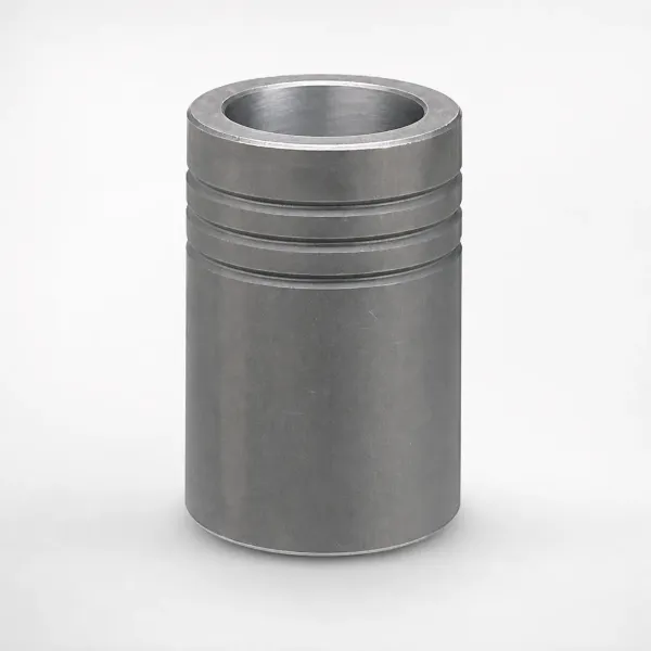
Grain flow is why forging beats machining from bar. Upset metal follows the part contour instead of being cut through. A connecting rod with uninterrupted fiber lines across the fillet carries 20 to 40 percent higher fatigue strength than a machined one. The die designer steers streamlines through blocker and preform geometry. Target a final draw ratio above 2 to 1, with grain flow within 15 degrees of the principal load axis.
Fill order is a die feature, not a press adjustment. A blocker station that pre-routes 60 to 80 percent of the volume into the heavy zones leaves the finisher a small, controlled upset. Without it, the finisher drives everything through the flash land. The land then works as a nozzle that erodes itself, the same shaping-before-closing rule as the deep draw die guide.
Die Steel and Heat Treatment
H13, the 1.2344 chromium hot-work grade, is the default die material. It survives repeated heating to 500 °C surface temperature without softening out of its working band. Die blocks run 44 to 52 HRC, with finisher inserts and high-load noses at 48 to 54 HRC. Temper at 580 to 620 °C so service heat never exceeds the temper. Otherwise the face anneals back 4 to 6 HRC per hot cycle.
Hardness is a trade, not a target. A die at 54 HRC resists abrasive washout about twice as long as one at 44 HRC. Its tolerance for thermal shock drops with it. A cold-start hammer strike at 54 HRC can crack a fillet on day one.
Hammer dies, thermally abused between blows, run the 44 to 48 HRC band. Press and line dies, stable between strikes, run 48 to 52 HRC.
Maraging inserts at 48 to 54 HRC hold sharp edges on the thin, high-stress nose sections where H13 washes out. Nickel-barrier diffusion coating grows a 0.2 to 0.3 mm hardened case on wear zones. Distortion stays under 0.05 mm on the impression. The 6 percent chromium standard family covers the aluminum side of the house. The full grade decision sits in the hot-work comparison of H13 vs H11 vs 1.2367.
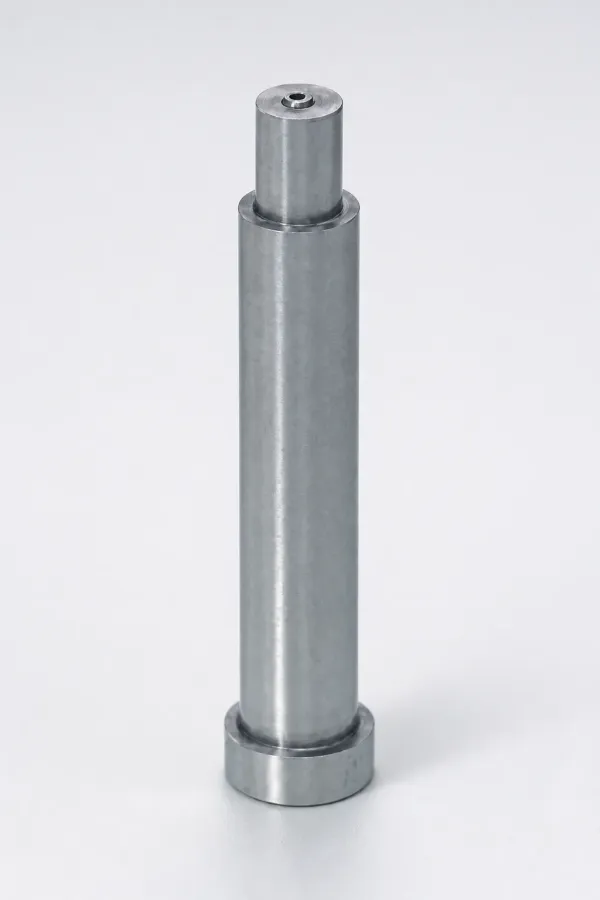
Buy die blocks pre-hardened, then stress-relieve roughing cuts at 600 °C. Leave 0.3 to 0.5 mm of grind or EDM stock on every impression face. Cut the impression after heat treatment, in the hardened condition. A 1.2344 block finish-machined before hardening moves 0.2 to 0.8 mm across a 200 mm span, and that movement is the die tolerance. We hold the finishing loop to +/-0.005 mm, with +/-0.002 mm on the EDM and jig-boring passes that cut gutters and pilot fits.
Die Temperature and Heat Checking
Thermal fatigue kills hot forging dies, and the temperature window is the control. Steel dies run preheated to 200 to 350 °C before the first billet, then settle at a 300 to 450 °C working surface. Aluminum warm-forging dies run 30 to 80 °C. That is why the aluminum ledger reads like a wear problem and the steel ledger reads like a cracking problem.
A cold die insults the whole process. At room temperature the block pulls heat from the billet in the first 0.5 to 2 seconds of contact. The chilled flash skin folds into the part as a cold shut. Meanwhile the die face cycles 25 to 150 °C per strike, and that amplitude nucleates heat-check cracks.
Preheat by induction, oven or torch. Spend 20 to 50 billets as a logged warm-up.
Heat checking is micro-cracking of the impression surface, 0.1 to 0.3 mm deep, in a network across the hot zones. Without coat and temperature control it appears after 1,000 to 3,000 parts. The cracks print as scale ridges into the forging. By 5,000 to 8,000 strikes the checked face sheds flakes that weld flash into the gutter. The countermeasures, in order: hold the band, keep the coat film, cap peak temperature with circuits.
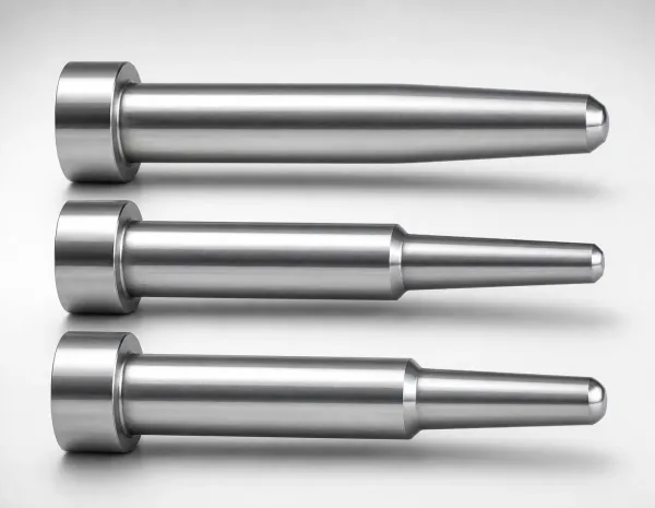
Measure the die instead of assuming it. A production set earns 8 to 20 thermocouple positions across the parting line. Above 500 t, read a pyrometer every cycle. Required positions sit at the flash land, the heavy boss zone and the last-fill corner.
On air-cooling hammer dies, read 10 to 15 spots per shift with a handheld infrared gun against the preheat floor. The same mapping logic sizes circuits in die casting die cooling design, with steel doing the work here.
The Wear and Failure Ledger
Hot forging dies fail in five repeatable modes, each with a measurable signature. Thermal fatigue from the temperature window is the default killer on steel work. Abrasive washout removes 0.05 to 0.2 mm of die steel per 1,000 parts at the land. Oxide-rich aluminum billet scours the face.
Plastic deformation of a thin land over 52 HRC reads as a bright, rolled edge under a 20x loupe. Gross fracture appears at cold starts and at stress risers under 3 mm inside radii. Galling shows on stainless as metal pickup within 200 to 500 strikes when the coat is missed. It strips the impression finish as fast as the metal welds to it.
Weld rebuild is the recovery plan. Repair checked or washed faces with hot-work consumables, re-temper at 580 to 620 °C, re-machine the impression. Blocks return 2 to 4 times to service, funded by 3 to 6 mm of block height.
| Failure mode | Die-side cause | Number to watch | Countermeasure |
|---|---|---|---|
| Heat checking | Surface cycling outside 300 to 450 °C band, coat skipped | 0.1 to 0.3 mm cracks after 1k to 3k strikes | Preheat, die coat, circuit trim |
| Land washout | Thin land plus scouring flow on aluminum | 0.05 to 0.2 mm per 1k parts at the land | Thicker land, harder insert, flitch check |
| Fillet wear | Radius under 3 mm concentrating the upset load | 0.10 to 0.15 mm per 1k on rib corners | Radius up to nominal wall, insert swap |
| Cold-start fracture | Strike on a die below 200 °C at 52 HRC | Preheat floor 200 °C, warm-up 20 to 50 billets | Induction preheat, start-up log |
| Galling pickup | Stainless flow welding to an uncoated face | Pickup within 200 to 500 strikes | Coat every strike, lower die hardness |
← swipe to scroll →
Table note: wear rates and life thresholds are typical industry values for H13 hot forging dies. Log strike counts, die temperature and coat coverage from the first production part, because the bands above only hold when the record exists.
Die life budgets fall out of this ledger. Expect 5,000 to 15,000 strikes on aluminum impression dies and 10,000 to 40,000 on steel dies run inside the window. High-volume press work clears 30,000 with rebuilds between surveys. A life promise of 1,000 parts on a production steel job is a design or process defect, not a steel-grade problem.
Die Coat and Cooling Circuits
The die coat is a consumable that protects a capital asset. Graphite or colloidal graphite lube sprays at 10 to 60 g/L solids between strikes. The film throttles heat into the die face. It lubricates flow across the land and holds the flash skin off the impression.
Use water-based graphite on steel work, and a low-flash-point synthetic on aluminum at 30 to 80 °C. No coat at all is how galling starts inside 500 strikes. Over-spray chills the face, fill drops short at the far corner, and the forger raises press force. That raises land wear. Under-spray lets billet scale weld onto the land, and washout rate doubles within 1,000 parts.
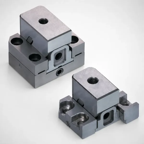
A spray robot with 2 to 4 nozzle passes per strike holds the film in the window. Time the spray 3 to 6 seconds after ejection. A hand lance cannot repeat that timing. Internal cooling carries the heat the coat cannot.
Air, mist or steam circuits drill 25 to 40 mm from the working face. Run them at a 15 to 25 mm pitch, sized 8 to 16 mm. Plumb the heavy boss zone on its own circuit. A 630 t steel die sheds 100 to 300 kW into the block on a steady cycle. Without circuits the face creeps 50 to 80 °C above the 450 °C ceiling within 200 strikes.
Keep circuit-to-face distance above 25 mm. Closer, and the drill breaks into the impression as a leak path. Thermal amplitude and crack density are coupled. Every 25 °C removed from the per-strike swing roughly halves heat-check initiation across the 1,000 to 10,000 strike band. Circuit layout, coat and preheat log are one control plan, not three.
When a checked face must come back, grinding removes 0.2 to 0.4 mm per pass. The impression survives 2 to 4 regrinds before retirement to rebuild.
Multistage Die Sets and Trimming
Production forgings move through a station chain. Cutoff, blocker or edger, preform, finisher, then a separate trim die. The blocker and preform stations carry 60 to 80 percent of the volume routing. The finisher then closes on near-net metal with a 5 to 10 percent upset.
Every station is a die set you pay for. A 4-station connecting rod set runs 25,000 to 60,000 USD, and the finisher holds the tightest prints. Die shoes and guidance keep the chain aligned. Blocks sit in shoes with 15 to 30 mm of per-side support under the impression edge, keyed or clamped. The trim die runs on guide posts with 0.05 to 0.10 mm sliding clearance, plus shutters on hammer sets.
Hammer dies live in blocks with the flitch angled 5 to 8 degrees. Shut height runs to +/-1 mm on hammers, controlled by set height. One millimeter of over-close punches the lands together and spalls the gutter radius.
Trim mismatch is the tolerance the trim die inherits. The flash witness line must sit inside a 0.1 to 0.3 mm band after trim. Locating pads grip two forged bosses at 0.05 to 0.10 mm clearance to hold that band. A trim die that locates on a machined surface is a scrap generator, because that surface does not exist yet at trim time.
Trimming runs on a 50 to 250 t press at 3 to 8 percent of the upset force. Cutter steel carries the same 44 to 52 HRC hot-work spec as the impression blocks.
Tolerance Reality and Die Correction
Set the tolerance promise before the die is cut. As-forged steel parts hold +/-0.2 to 0.7 mm on linear dimensions, with 0.3 to 0.5 mm parting-line mismatch. Flashless multistation work is 30 to 50 percent tighter. The machining allowance left on the part is 1.5 to 4 mm per face.
A drawing that demands 0.1 mm straight off a hammer is not a forging print. It is a machining print written on the wrong process.
Two physical effects consume the tolerance budget. Thermal shrink from 1,050 °C to ambient draws the part down 1.0 to 1.5 percent on the layout dimension. The impression is grown by that factor at design. Die wear then walks the part back.
A land at 1.0 mm opens to 1.3 mm after 8,000 strikes. Flash force drops, and the fill corners soften before the CMM flags anything.
Correction is a loop with a schedule, not an emergency. Survey the forging on a CMM every 2,000 to 5,000 strikes, using 3 to 5 mm datum pads. Compare each survey against the grown print. Grind or weld the face inside the 3 to 6 mm of block height the die was built with.
A die needing its third correction before 10,000 strikes says the shrink factor, land geometry or temperature window is wrong. That fix belongs in the next die, not the third rebuild.
How DieStrike Tools Hot Forging Dies
DieStrike is the precision die shop you commission the tooling from. The forging press, induction heater and trim line belong to the forger. The impression geometry, die material and hard-machining accuracy are ours to deliver.
We build die blocks, inserts and trim dies under an IATF 16949 quality system. The shop runs 120+ machines and holds +/-0.005 mm on finished die geometry. EDM and jig-boring passes that cut gutters, lands and pilot fits hold +/-0.002 mm.
Capability maps directly to this guide's rules. Heat treatment runs to HRC 62 maximum on inserts and high-load nose sections. Standard components source in 3 to 7 days, and die lead times run 2 to 5 weeks from an approved print. Tier-1 programs with TE, Amphenol, Luxshare and Dongshan run on the same design-review and first-article discipline.
The impression is CMM-reported against the grown layout before the die ships. Land, flitch and radius callouts appear on the report. Send the part print through stamping die manufacturing. The quote comes back with a DFM list of shrink factor, draft and radius proposals, not only a price.
The Bottom Line
Hot forging die life is bought in four decisions made before the first billet. Set the flash land at 0.4 to 1.5 mm. Use a 5 to 8 degree flitch and a 1 to 3 mm gutter radius, so the land meters the fill instead of washing out.
Give the impression 3 to 7 degrees of external draft and 5 to 10 internal. Use fillets of 3 to 8 mm matched to the wall. Cut the blocks from H13 at 44 to 52 HRC, tempered at 580 to 620 °C, machined after hardening to +/-0.005 mm.
Preheat the die to 200 to 350 °C and hold a 300 to 450 °C working band. Run graphite coat and circuits at 25 to 40 mm from the face. With those numbers the ledger reads 10,000 to 40,000 strikes on steel and 5,000 to 15,000 on aluminum, with trim mismatch under 0.3 mm throughout. Skip them and the same die set dies at 2,000 strikes.
The press belongs to the forger. The die geometry belongs to whoever cuts the impression. The difference between 2,000 and 20,000 parts lives in that shop's drawings, temperature logs and CMM reports, before the first strike.
KEEP READING
Related Reading
How to Design Hot Stamping Dies
Press-hardening tooling for 1,500 MPa boron steel: quench channels, coatings and springback at temperature.
Read articleArticleHow to Design Transfer Dies
Station chains, gripper timing and mismatch control on multi-station hot forming lines.
Read articleArticleH13 vs H11 vs 1.2367 Hot-Work Tool Steel
A composition, hardness and thermal fatigue comparison of the three hot work grades.
Read articleServiceStamping Die Manufacturing
IATF 16949 die shops with 120+ machines, +/-0.005 mm accuracy and 2 to 5 week tool lead times.
View serviceNEXT STEP
Ready to Start Your Mold?
Send us your element dimensions or part numbers — our team responds within 24 hours. Pricing and lead time come with the answer.

Written by
Ray ChanExport Brand Manager at DieStrike. Ray helps global importers, distributors and OEMs source factory-direct molds and mold parts.