
How to Design Low-Pressure Die Casting Dies: LPDC Tooling
Table of Contents
A wheel die built like a high-pressure die casting die pushes melt into the rim at 40 m/s, entrains a film of gas, and the part blisters on the first T6 solution cycle at 520 °C. The fix is a die that fills at 0.02 to 0.05 m/s through a dip tube and holds 1 to 3 bar of intensification for 30 to 120 seconds while the boss freezes. This guide sets out the LPDC die numbers: tube geometry, chamber sealing, thermal balance without spray, and die steel.
Every figure is a typical industry value for aluminium LPDC tooling, checked against the alloy, the part section and the machine cell before a die drawing is released.
The Snapshot
- Fill pressure is 0.06 to 0.8 bar, not 150 bar. That over-pressure lifts 2,400 kg per m3 aluminium melt through 0.25 to 3.4 m of static head and drives the melt front below 0.02 to 0.05 m/s, roughly 1,000 times slower than a high-pressure in-gate jet.
- The dip tube is the gate, at 40 to 80 mm bore. A tube mouth flush or 0.5 to 1 mm proud of the parting line, with a 1.5 to 3 mm cell filter screen, decides where the shrink pore lands.
- Intensification is 1 to 3 bar for 30 to 120 s. With no biscuit to freeze off, the feeder must stay liquid until a 20 to 40 mm boss finishes solidifying.
- Die life runs 60,000 to 200,000 shots on a wheel die. H13 1.2344 at HRC 44 to 50, no water spray and no soldering, because metal velocity at the die face stays under 1 m/s.
What Low-Pressure Die Casting Actually Is
Low-pressure die casting fills a sealed die from below with dry air or nitrogen. Melt rises from a holding furnace through a dip tube into a top-fed cavity. Fill pressure runs 0.06 to 0.8 bar above atmosphere, just enough to lift the metal the height of the tube plus the cavity. There is no shot sleeve, no plunger and no biscuit.
The furnace is part of the tooling decision. A hold-on furnace carries 2 to 8 t of melt and clamps to the machine structure, so die, tube and furnace form one sealed system that rotates together. That is counter-gravity LPDC, and it is why a wheel die has no runner to trim. In the bottom-pour variant the furnace stays fixed while the die rotates through 90 to 180 degrees.
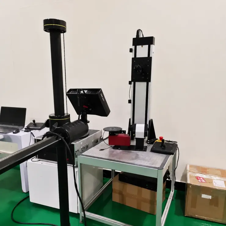
Filling speed separates LPDC from every high-pressure route. A cold-chamber gate runs melt through the orifice at 30 to 60 m/s. LPDC runs the melt front at 0.02 to 0.05 m/s, filling a wheel rim in 5 to 15 s. At that velocity the surface film is not broken into chips, so oxide and gas entrainment drop by orders of magnitude.
The consequence for the die designer is structural. There is no overflow, no runner to size, no biscuit to chill. There is a tube, a screen, a sealed chamber, and a thermal balance that works without spray on the cavity face.
Where LPDC Beats High-Pressure Die Casting
LPDC earns its place in three situations. The first is a part that must be heat treated. A solution treatment at 520 to 540 °C for 1 to 4 h lets an entrapped-gas casting blister: gas inside the metal expands, the surface lifts, the part is scrap. Near-zero entrapped gas is what makes an LPDC A356 part T6-able, and why a steering knuckle is an LPDC part.
The second is weldability. A battery tray or e-motor housing gets welded after casting, and porous weld zones on gas-filled die castings throw 3 to 10 percent of parts into repair scrap. Wall floors go to 1.5 to 2.5 mm on LPDC. The part list says it plainly: wheels at 6 to 14 kg, intake manifolds, knuckles and battery trays, X-rayed against ASTM E155 reference radiographs in 8 to 20 mm sections.
The third is yield. With no biscuit and no overflows, an LPDC wheel puts 90 to 95 percent of poured metal into the part, against 60 to 75 percent for a cold-chamber shot.
| Route | Fill velocity at gate | Gas and heat treat | Min wall | Cycle |
|---|---|---|---|---|
| LPDC counter-gravity | 0.02 to 0.05 m/s | Near-zero entrapped gas, T6 capable | 1.5 to 2.5 mm | 3 to 8 min |
| Vacuum-assisted HDC | 30 to 60 m/s with vacuum help | Low gas, T1 or modified T6 | 1.5 to 2 mm | 60 to 120 s |
| Gravity permanent mold | 0.1 to 0.3 m/s, head only | Low gas, full heat treat | 3 to 4 mm | 4 to 10 min |
| Cold chamber HDC | 40 to 80 m/s | High gas, no T6 | 1.0 to 1.5 mm | 45 to 90 s |
← swipe to scroll →
Table note: velocities, wall floors and cycles are typical industry values for aluminium parts. Read the route choice against the part's heat-treat spec and X-ray grade before a die is quoted. The gate mechanics of the high-pressure side sit in the hot chamber vs cold chamber guide.
The decision rule is short. Buy LPDC when the part must be T6, welded or X-ray clean and the cycle can afford 3 to 8 minutes. Buy high-pressure when the wall is under 1.5 mm or the rate needs a sub-90 second cycle.
The Dip Tube Is the Gate
In LPDC there is no sprue, no runner and no biscuit. The dip tube does the job all three do on a high-pressure die, so its geometry belongs on the drawing with the discipline a gate size gets. Bores run 40 to 80 mm, sized so the full pour mass rises through the tube inside the 5 to 15 s fill window without the melt front passing 0.05 m/s. A 40 mm tube under a 15 kg wheel pour pushes the front past 0.05 m/s and folds dross into the rim.
The tube mouth sits flush with the parting line, or 0.5 to 1 mm proud. Flush keeps the mouth a clean hole in the seal face. Proud by 0.5 to 1 mm buries the tube rim into the die so melt cannot creep under it and freeze the chamber joint. Deeper than 1 mm and the mouth edge becomes a heat sink.
At the mouth, a filter screen with 1.5 to 3 mm cells holds dross back from the cavity. The screen must not freeze shut during the hold, so frames go in nitrided or BN-coated steel, seated so a change is a 20 minute job. Budget a screen-frame replacement every 10,000 to 20,000 shots.
Tube wear sets the change schedule. A steel tube in 720 °C A356 loses about 0.1 mm of wall per 10,000 shots, so a 10 mm wall budgets 100,000 shots. A BN-coated tube lasts 2 to 3 times that. Gate freeze and packing couple through the same tube: once the mouth collar closes, the cavity is cut off from the furnace no matter what the gauge reads.
Keep tube-mouth concentricity to the sealing bore inside 0.1 mm, or melt jets along the low side of the gap. Screen and mouth belong on replaceable inserts: both see 690 °C contact for a full cycle.
Intensification, Hold and Shrinkage
LPDC runs two pressure stages, and the die must respect both. Fill happens at 0.1 to 0.3 bar above static head until the cavity is full. Then intensification jumps the chamber to 1 to 3 bar and holds 30 to 120 s while the thickest section freezes. The hold is set by the heaviest boss: a 20 to 40 mm solid section needs that window, because shrinkage feeding only works while metal in the tube is liquid.
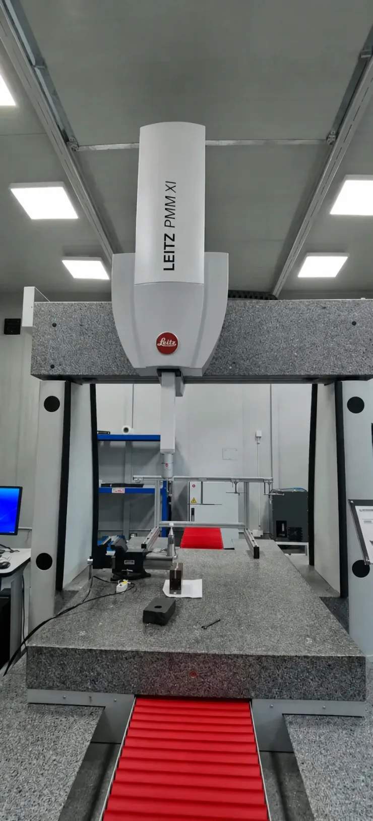
A cold-chamber die freezes its biscuit in 1 to 2 s, and after that the cavity is sealed from the machine. An LPDC die keeps a live liquid path from furnace to cavity for the whole hold, so the tube mouth and screen stay in hot metal for 1 to 2 minutes every shot.
Locating the shrink pore is a tube design act. Solidification must progress so the last liquid point lands inside the fed volume, ideally just above the tube mouth. On an A356 wheel the hub freezes in 60 to 90 s and the rim in 20 to 40 s, so the tube mouth at the hub centre feeds the hub for its whole freeze. If feeding stops early, even 1 to 3 bar pulls a shrink cavity at the last hot corner, and X-ray reads it as a round void.
Feed efficiency is calculable. Keep total mouth flow area at 3,000 to 5,000 mm2 for sections above 25 mm, and freeze-proof the screen frame with a 3 to 5 mm steel lip. Pressure loss between gauge and metal is the number nobody puts on the drawing: every metre of tube adds 0.12 bar of static head at 2,400 kg per m3, and a half-plugged screen moves effective fill pressure by 0.1 to 0.2 bar and prints a slow-fill misrun at the far rim. The porosity guide covers telling shrink voids from gas pores.
Die Thermal Management Without Spray
A cold-chamber die balances heat with water spray: 50 to 200 ml per shot of atomised air-water hits the cavity face. An LPDC die cannot take that. The chamber is sealed and pressurised, the die often rotates, and spray would pool in the tube and flash-steam on contact with 690 °C melt. The die must move heat internally, and the internal layout is where LPDC tool design differs most from high-pressure design.
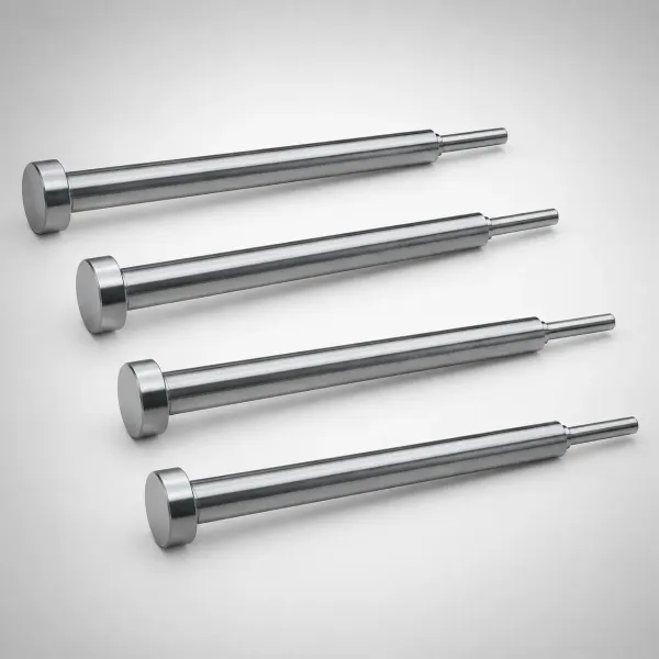
Three paths carry the heat. Conduction and radiation into the die block set the baseline. Internal steam, closed-loop water and compressed-air circuits drilled into the die back do the active work. The water leaves as steam inside a sealed chamber and returns through a condenser loop.
Preheat the die to 180 to 260 °C before first pour and run the cavity surface inside a 200 to 350 °C band. Below 180 °C the metal freezes the tube mouth early and starves the hub. Above 350 °C the rim sections never set and the cycle stretches past 8 min. An HDC die face sees 400 to 550 °C peaks between sprays; the LPDC face runs steadier, so heat checking is slower here.
Instrument the last-fill corner, not the middle. Thermocouples belong at the far rim and under the feeder, 10 to 15 mm from the face, because those points decide misrun and shrinkage. Two to four Type-K or Type-N holes per die half give the control loop its read; one center thermocouple hides a 50 to 80 °C imbalance across a 500 mm wheel face.
Circuit scaling keeps 15 to 25 mm of steel between cavity surface and closest channel, with 12 to 20 mm bores on a 50 to 80 mm pitch. Under the feeder, add a hot-spot insert of nitrided H13 or a metallic chill at 2 to 4 times the local wall mass, so the last liquid metal sits in the feeder land. The die cooling design guide covers the sprayed HDC case.
Die Steel, Hardness and Life
H13 (1.2344) at HRC 44 to 50 is the standard LPDC die material. The face never sees 60 m/s metal, soldering is a non-issue under 1 m/s, and thermal amplitude per shot is small. Pre-hardened 1.2343 at HRC 40 to 44 is acceptable on housings under 30,000 shots. Steel choice is priced out in die casting mold steel selection.
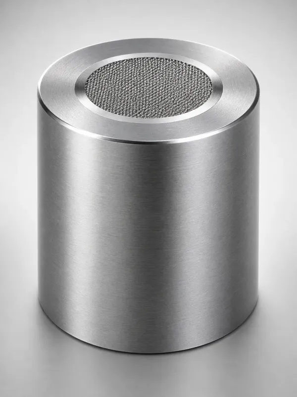
Why HRC 44 to 50 rather than the HRC 62 a stamping die carries? Above HRC 52, hot-work steels lose thermal fatigue resistance fast. Heat checking is the real life limit: a 40 to 80 °C surface amplitude every 3 to 8 min cycle, 60,000 to 200,000 times. At HRC 46 cracks stay shallow and the die takes a weld repair; at HRC 52 the same cracks grow to 0.3 mm and the insert is scrap.
Nitriding is the optional upgrade. A plasma-nitrided skin of 0.4 to 0.6 mm with a 0.08 to 0.15 mm white layer raises the surface to 1,000 to 1,200 HV and adds 30 to 50 percent to tube-mouth and feeder-land life. The trade is repair difficulty: weld repair through a nitrided layer needs re-nitriding.
Life bands: an aluminium LPDC wheel die runs 60,000 to 200,000 shots between rebuilds, against 100,000 to 500,000 for rebuilt steel dies. LPDC removes two classic casting-die failures, soldering and gate washout, because face velocity stays under 1 m/s. It does not remove thermal fatigue, and a die is usually retired by crack depth on the feeder land. Plan rebuilds around weld repair at 580 to 620 °C temper, and keep the last-fill corners in replaceable inserts.
Cavity Layout and Chamber Sealing
A counter-gravity station carries 1 to 4 cavities, and each cavity gets its own dip tube. LPDC balances fill by tube count and bore, not by runner trim. A twin wheel die runs two 50 to 60 mm tubes with mouth areas matched within 5 percent, so both rims finish inside the same 5 to 15 s window. An unbalanced high-pressure part is fixed with runner tabs; in LPDC the part is re-tubed or the die is re-machined.
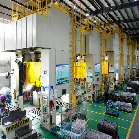
Put the feeder under the heaviest section, then keep the tube path straight. The tube axis meets the parting line at the hub, riser boss or flange centre, with 1 to 2 degrees of draft on every core. Core pins for bolt bosses run 8 to 15 mm in bore, H13 at 0.05 to 0.10 mm running clearance. Ejection strips on the hub flange, 6 to 12 pins at 15 to 25 kN combined on a wheel.
The chamber is a pressure vessel and the die is its head. Seal it like one: a tube-to-die clamp with a graphite or flexible-metal ring, parting-line seals holding 0.8 bar with a 2x margin, rotary joints on bottom-pour cells rated for 100,000 cycles. The acceptance test is unforgiving: pressurise to 0.8 bar and read decay, under 0.02 bar over 30 s, or a vacuum hold at 0.5 mbar absolute with no rise for 60 s. A die that leaks 0.05 bar in 30 s will fill short at 0.15 bar.
Machine Interface and Cycle Economics
LPDC clamps at 60 to 400 kN because the die never sees high-velocity counter-pressure. A 0.4 m2 projected area under 0.8 bar carries roughly 32 kN of separating force, so clamp size follows rotation and ejection loads. The same wheel in cold chamber needs a 1,600 to 4,000 t press and a biscuit.
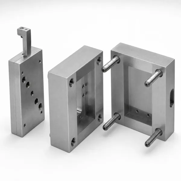
A 3 to 8 minute cycle buys soundness back in clock time. A typical 5 minute wheel cycle spends 5 to 15 s filling, 30 to 120 s intensifying, 120 to 300 s cooling to about 150 °C surface, then 30 to 60 s rotating, opening and stripping. A cold-chamber cycle fills the same wheel in under 5 s and still cannot be T6 treated.
Tool cost sits at 25,000 to 120,000 USD for a single to twin cavity LPDC die on a drilled die-block base. Consumables are real numbers: 0.1 mm of tube wall per 10,000 shots, a screen frame every 10,000 to 20,000 shots, die wash metered every 5 to 20 shots. Metal yield of 90 to 95 percent against the 60 to 75 percent of biscuit routing usually pays for the slower cycle on any part above 5 kg.
Route the decision the way you route a trial. If the part is a knuckle, wheel, manifold, battery tray or e-motor housing and the print says T6, weld or X-ray, put the tube, seal and thermal-balance numbers on the drawing before anyone quotes a furnace. Buyer-side T1 packages for casting tooling are specced under die casting mold manufacturing.
Common LPDC Die Failures
LPDC defects cluster around the tube, the seal and the thermal balance, and each carries a read-off number. Run this ledger against a struggling cell before the die goes back to the machining shop.
| Failure | Root cause in the die | Number to check |
|---|---|---|
| Misrun at the far rim | Plugged screen or chamber leak eating fill pressure | Decay under 0.02 bar in 30 s at 0.8 bar; screen cells 1.5 to 3 mm |
| Round shrink void in the hub | Hold too short or tube mouth frozen before the boss set | 1 to 3 bar for 30 to 120 s matched to a 20 to 40 mm section |
| Blistering after T6 | Fill above 0.8 bar, melt front over 0.05 m/s, oxide entrained | Fill 5 to 15 s; tube bore 40 to 80 mm sized to pour mass |
| Heat checks on the feeder land | Surface above 350 °C, no hot-spot insert, amplitude too high | Band 200 to 350 °C; insert at HRC 44 to 50; cracks under 0.1 mm |
| Pressure loss on rotation | Tube clamp ring or rotary joint wear in the sealed chamber | 0.5 mbar vacuum hold for 60 s; joints rated 100,000 cycles |
| Tube failure mid-production | Uncoated steel at 0.1 mm wear per 10,000 shots, wall thinned out | 10 mm wall budgets 100,000 shots; BN coating lasts 2 to 3x |
← swipe to scroll →
Table note: pressures, times and wear rates are typical values for aluminium LPDC wheel and housing dies. Confirm them against the alloy datasheet, the cell's pressure recorder and the X-ray grade before cutting steel.
Two rows are one mistake at different stages. A misrun at 0.15 bar effective pressure and a blistered part after T6 both mean the fill system is not doing what the drawing says: one has too little pressure reaching the metal, the other too much velocity inside it. Check the seal before the screen, and the screen before the tube bore.
The third pattern is time, not geometry. Shrink voids appearing only on the third shift point at a feeder land warmed 30 to 50 °C above trial as the wash schedule slipped. A drifting thermocouple says clean a circuit, not re-machine the cavity.
LPDC Die Design Checklist
Run this list against the die drawing before release. Every line is a number a reviewer reads off the print, not the furnace log.
- Route and furnace fit. Counter-gravity or bottom-pour, 2 to 8 t hold-on or fixed furnace, rotation axis drawn on the parting-line view.
- Tube as gate. 40 to 80 mm bore sized to pour mass, mouth flush or 0.5 to 1 mm proud, screen cells 1.5 to 3 mm, wear allowance 0.1 mm per 10,000 shots.
- Two pressure stages. Fill at 0.1 to 0.3 bar, intensification at 1 to 3 bar for 30 to 120 s matched to the heaviest 20 to 40 mm section.
- Feeder location. Mouth under the last-freezing boss, hot-spot insert at 2 to 4x local wall mass, shrink path drawn into the feeder land.
- Thermal balance without spray. Preheat 180 to 260 °C, band 200 to 350 °C, circuits 15 to 25 mm behind the face, thermocouples at the last-fill corner and under the feeder.
- Steel and hardness. H13 1.2344 at HRC 44 to 50, optional nitriding 0.4 to 0.6 mm on feeder lands, replaceable inserts where heat check concentrates.
- Chamber seal. Decay under 0.02 bar in 30 s at 0.8 bar, or a 0.5 mbar hold for 60 s, in the acceptance test.
- Ejection and draft. 1 to 2 degrees of draft, hub-flange stripping sized in kN, no bare pin on a 1.5 to 2.5 mm wall.
- Life and rebuild plan. 60,000 to 200,000 shot band, tube and screen on a consumables schedule, weld repair stated with its 580 to 620 °C temper.
- Acceptance evidence. Pressure-recorder trace, 12-point wall check, X-ray to the print's ASTM E155 class, leak test in the die file.
The checklist is also the handover file. A die that ships with its leak-test record, thermocouple map and tube schedule restarts the same after a furnace move.
The Bottom Line
LPDC die design stands on four numbers. The dip tube is the gate, 40 to 80 mm bore with a 1.5 to 3 mm screen and a mouth flush or 0.5 to 1 mm proud. Fill runs at 0.1 to 0.3 bar with the melt front under 0.05 m/s, then intensification holds 1 to 3 bar for 30 to 120 s because there is no biscuit to seal the cavity. The die balances heat internally, 180 to 260 °C preheat inside a 200 to 350 °C band, because there is no spray. And the chamber is a pressure vessel, leak-tested at 0.02 bar in 30 s or 0.5 mbar for 60 s.
Buy the route for the metal, not the cycle. Near-zero entrapped gas is what makes a wheel, knuckle or battery tray T6-able and weldable at 1.5 to 2.5 mm wall floors, and it turns 90 to 95 percent of poured metal into saleable parts.
DieStrike makes LPDC dies, inserts and chamber tooling under an IATF 16949 quality system: plus or minus 0.005 mm mold accuracy, plus or minus 0.002 mm on EDM and jig grinding, HRC 62 maximum heat treatment, 120+ machines, standard components in 3 to 7 days and tool lead times of 2 to 5 weeks, with tier-1 references including TE, Amphenol, Luxshare and Dongshan. Your foundry runs the furnace; we make the die.
KEEP READING
Related Reading
Hot Chamber vs Cold Chamber Die Casting: How to Choose
Gate velocity, shot timing and die steel numbers for the two high-pressure routes, read against the LPDC case.
Read articleArticleHow to Reduce Die Casting Porosity: Gas, Shrinkage and X-ray
How to tell entrapped gas pores from shrinkage pores and what each one says about the gating you chose.
Read articleArticleHow to Design Die Casting Die Cooling: Thermal Balance and Die Life
Circuit scaling, steel wall rules and temperature bands for dies that run with water spray.
Read articleServiceDie Casting Mold Manufacturing
IATF 16949 die and insert making with plus or minus 0.005 mm accuracy and 2 to 5 week tool lead times.
Read articleNEXT STEP
Ready to Start Your Mold?
Send us your element dimensions or part numbers — our team responds within 24 hours. Pricing and lead time come with the answer.

Written by
Ray ChanExport Brand Manager at DieStrike. Ray helps global importers, distributors and OEMs source factory-direct molds and mold parts.