
How to Design Molds for Plated Plastic Parts: ABS, PVD and Vacuum Metal
Table of Contents
A 0.05 mm flow line you can barely read on raw ABS becomes a dark streak once the part returns from the copper-nickel-chrome line, and the rework starts at the plater, not at the press. Plating sorts parts by fill history, molded-in stress and surface energy, then bills the miss as a 1 to 5 percent cosmetic reject rate plus a bath load you cannot recover. This guide sets the mold-side numbers that keep a Class A cosmetic part through etch, strike and plate.
Every figure below is a typical industry value for plated-part tooling, and each one needs checking against the resin datasheet and the plater's own spec before a drawing is released.
The Snapshot
- Plate total of 15 to 30 µm. A standard ABS sequence lays copper at 5 to 15 µm, semi-bright nickel at 5 to 10 µm, bright nickel at 2 to 8 µm and chrome at 0.25 to 0.5 µm, so the metal copies the plastic surface it lands on.
- Keep molded-in stress under 40 to 60 MPa. Adhesion fails above that band and at release-agent residue, and ASTM B604 style thermal cycling from -20 to +70 °C pulls the weak plates off first.
- Gate land 0.4 to 0.8 mm, vent land 0.02 to 0.04 mm. A submarine or tangential gate hides its witness in a non-cosmetic rib, and any vent deeper than 0.04 mm flashes and plates as a burr.
- Mold 60 to 80 °C on the cosmetic zone. Plating parts often need a 60 to 90 °C post-mold anneal of 2 to 4 h to drop stress, so the cavity must hold shape and gloss at temperature.
Why Plating Magnifies Mold Defects
Electroplating starts in an etch bath of chromic and sulfuric acid that attacks only the rubber phase dispersed through ABS. The bath micro-roughens the surface so palladium can anchor and metal can grip. A defect that reads as nothing on raw plastic absorbs the etch differently and survives as contrast.
A 0.05 mm flow line, a shallow gate blush or a faint die line is a cosmetic scrap after copper-nickel-chrome, because metal reflects specularly and depth reads as shade. The deposit sequence amplifies the surface: copper at 5 to 15 µm, semi-bright nickel at 5 to 10 µm, bright nickel at 2 to 8 µm and chrome at 0.25 to 0.5 µm.
Molded-in stress is the second magnifier. Adhesion fails above roughly 40 to 60 MPa, and sink, weld lines and over-packed bosses all concentrate stress in exactly the places a cosmetic part cannot hide it. Release-agent residue is the third: silicone film survives cleaning in many shops and blocks the etch, so only silicone-free releases belong near a plated part.
Verification is unforgiving. Thermal cycling between -20 and +70 °C and copper-accelerated corrosion tests pull weak plates off in the lab so they cannot pull off in the field, and tab-pull adhesion on automotive trim is commonly specified at 8 to 20 N/mm. Anything under the agreed band scraps at the plate line, where the part is worth several times what it was worth as plastic.
The Two Plating Routes and What Each Demands of the Mold
Two routes put metal on plastic, and each writes a different instruction into the mold. Route one is electroplating on ABS or an ABS-PC alloy. The part runs etch, palladium activation, copper, semi-bright nickel, bright nickel and chrome, a total of 15 to 30 µm. The mold wants 60 to 80 °C to hold gloss and relief stress, and the resin needs enough rubber phase for the etch to bite.
Route two is vacuum metallization and PVD, which deposits an aluminum layer of 0.02 to 0.1 µm under a primer lacquer of 5 to 20 µm and a topcoat of 10 to 25 µm. There is no chrome bath and no hex-chrome permit, and a 40 to 70 °C mold cycle sits inside the coating's heat window. The aluminum is soft, so a clear coat has to carry the abrasion duty.
| Item | Electroplated ABS | Vacuum metal and PVD |
|---|---|---|
| Typical resin | ABS or ABS-PC with a rubber phase the etch can bite | ABS, PC and PC-ABS, plus coated PP |
| Mold temperature | 60 to 80 °C for gloss and stress relief | 40 to 70 °C, cycle friendly |
| Coating build | 15 to 30 µm of copper, nickel and chrome | 0.02 to 0.1 µm aluminum plus 5 to 20 µm primer and 10 to 25 µm topcoat |
| Permit burden | Chrome bath, hex-chrome rules | No chrome bath, no hex-chrome permit |
| Abrasion defense | Chrome cap at 0.25 to 0.5 µm | Clear coat required over soft aluminum |
← swipe to scroll →
Table note: temperatures and layer builds are typical industry values. Confirm them against your plater's process spec and the resin datasheet before the mold design is frozen.
Route choice is a mold decision before it is a finish decision. It sets the mold temperature spec, the resin shortlist and where a witness mark is allowed. Fix it on paper first, because a tool built for a 60 to 80 °C electroplating cycle and a tool built for a 40 to 70 °C PVD cycle are different cooling designs.
Gate Design and Wash-Out Rules
The gate decides whether the part survives the etch. A direct-gated cosmetic face jets melt across the cavity, the frozen stream folds over itself, and that weld lines up as an etch-visible seam no process window removes. A submarine or tangential gate with a 0.4 to 0.8 mm land puts the witness below the parting line, and the layout rule lives in the gate vestige and cosmetic quality guide.
Hide the witness on purpose. Route the gate into a witness area the customer never sees head-on, or into a non-cosmetic rib or boss back, so the vestige and the shear bloom land on geometry the parting agreement already wrote off. A pinpoint gate on a three-plate tool concentrates stress at the freeze point and becomes a stress riser the bath exploits; on a plated part it is the wrong default.
Balance gates hard, because plating sorts parts by fill history. Cavities that fill 1 to 2 s apart from one another see different shear, different orientation and different trapped stress, and the etch reads those differences as tone variation across one plater load. Keep all cavities filling within 1 to 2 s, gate symmetrically, and check the balance on a mold-flow fill plot before the steel is cut.
Wash-out is the melt polishing the cavity surface ahead of the fountain flow. A 0.4 to 0.8 mm land running into open cosmetic area gives the wash-out room to disappear; a gate that dumps directly onto a visible face leaves a blush 0.5 to 2 mm wide that plates darker. The resin side of the decision, drying and rubber-phase content, sits in the ABS material guide.
Venting, Burn Marks and Release Discipline
Plated parts show burn marks that raw parts hide. A thin scorched film at the last-fill corner etches unevenly and plates as a dull stain, so vent discipline is a plating requirement, not just a molding one. Run 0.02 to 0.04 mm vent lands at the last-fill corner and at the end of every cosmetic flow path.
A vent deeper than 0.04 mm flashes, and the flash edge plates as a burr that handling cannot rub off without marking the chrome. A shallower vent plugs with residue between 20,000 and 50,000 shots. Put the vent in a non-cosmetic witness area wherever the layout allows, and write the clean interval into the maintenance sheet.
Thin cosmetic ribs fill last and burn first, so vacuum-assisted molding earns its cost on grilles and bezels with ribs under 1 mm. Pull the cavity to 0.2 to 0.5 bar below atmosphere just before fill and the gas leaves with the melt instead of compressing into the rib tip.
No mold spray goes on the cosmetic face, and only silicone-free releases live anywhere near this part. One silicone film survives many cleaners, blocks the chromic-sulfuric etch locally, and the plate lifts off that footprint in the B604 cycle. If the part sticks without spray, the answer is draft, polish or chrome on the tool face, not chemistry on the part.
Cooling and Molded-In Stress
Cooling sets the two numbers the plater tests first: gloss and molded-in stress. Hold the cosmetic zone at 60 to 80 °C for electroplated ABS, 40 to 70 °C for vacuum metal parts, and split the tool by zone so a deep rib block can run hotter than the visible face without dragging the whole plate with it.
Run the coolant at an 8 to 14 °C delta across the circuit. A hot spot on a cosmetic face welds gloss variation into the part before it ever sees a bath, and a 5 to 10 °C spread across a bezel face reads as a matte stripe after chrome. Baffles or bubbler lines in boss and rib country beat drilled dead-legs where the layout cannot reach.
Stress relief after the press is standard on plated parts: a 60 to 90 °C anneal for 2 to 4 h drops molded-in stress back under the 40 to 60 MPa adhesion limit. The cavity must not distort at that window, which is why the anneal spec and the steel heat treatment belong on the same drawing sheet, and why packing profiles that trade stress for sink are settled at the trial, not after plate.
Uniform wall carries the whole argument. Keep plated cosmetics at 0.8 to 1.2 mm with ribs at 50 to 60 percent of the local wall, so sink stays under 0.05 mm and the stress field stays symmetric. A 0.1 mm sink ring at a boss edge plates as a dark circle, and no anneal schedule erases it.
Steel and Surface Finish Choice
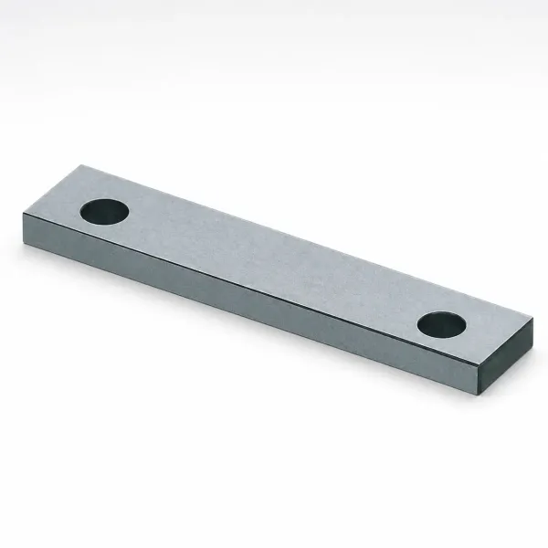
Pick steel by what the plater will do to the part, not by what the press will do to the tool. Cosmetic cavities in S136 or 420 hardened to 48 to 54 HRC hold a mirror face through an abrasive ABS and resist the occasional corrosive breakthrough. Backs, slides and lifters in P20 or 718 cost less per hour of machining and never touch the visible surface.
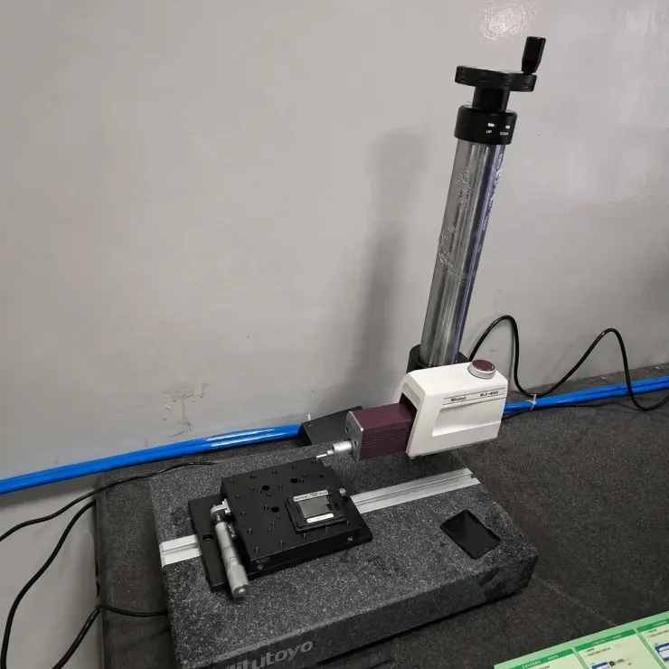
Polish the cosmetic cavity to SPI A1 to A2. Below that band, the steel's own grind marks etch and plate as a texture the print never called for. If the design calls for a matte metallic look, that texture is specified deliberately and matched on the mold texture specification guide; otherwise no texture goes on a plating face.
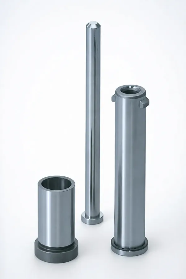
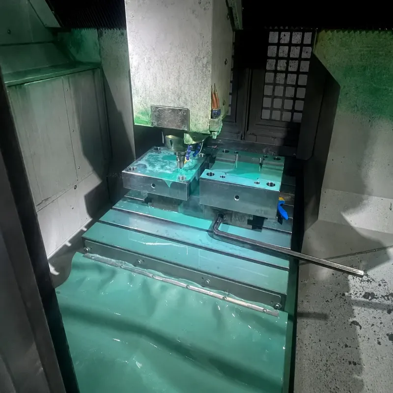
EDM leaves a re-cast white layer, and on a plating face that layer pits after the etch. Burn EDM features 0.05 to 0.10 mm oversize, then polish at least 0.02 mm below the discharge surface to clear the rescast layer, or spark and re-grind the detail. The trade between the discharge and the wheel is worked out in the EDM surface finish versus SPI texture guide.
Held to an IATF 16949 quality system on a floor of 120+ machines, we cut these faces to plus or minus 0.005 mm mold tolerance, with plus or minus 0.002 mm on the EDM and jig-grinding work that carries the gate land and the shut-off. Maximum heat treatment reaches HRC 62 when a shutoff edge needs it. That is tool-room capability stated plainly: we tool it, and the molder you buy from owns the press.
Ejection, Draft and Witness Placement
Ejector pin marks are permanent once a part is plated, because a 0.05 mm pin impression reflects light differently than the surrounding face. Land ejector pins on ribs, bosses and non-cosmetic geometry only, and where a visible face must be released, move to a stripper sleeve over the core or air ejection at parting.
Draft starts at 2 to 3 degrees on cosmetic walls plus 1 degree per 25 mm of depth, and the cosmetic face gets the better polish the deeper the draw. A 0.5 degree shortfall that a raw part shrugs off leaves a drag mark the etch turns into a scuff line. Polish drag and ejector witness are both written into the plater's first-article agreement, so nobody is surprised after 500 parts come out of the bath.
Parting-line die lines deserve the same treatment. Keep the shut-off overlap at 0.05 to 0.1 mm of steel-to-steel contact, locate the line off the visible silhouette, and never let a sharp die line cross a cosmetic face, because the etch bites the raised edge first and the chrome follows the bite. Gate witness, parting line and ejector points get agreed in writing with the plater before the drawing is released, which is the shortest definition of a plated-part DFM.
Cavity Count and Plating Economics
High-volume plated parts, grilles, bezels, mirror covers and switch surrounds, run 4 to 16 cavities, and the cavity count is set by the plating line as much as by the press. One plater load has to come from cavities that fill within 1 to 2 s of each other, so a 16-cavity tool that cannot balance to that window delivers 8 usable cavities and 8 tone outliers. Balance first, then count.
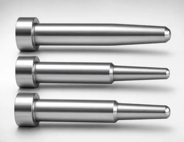
Wall geometry has a floor here. Keep plated cosmetics at 1.5 to 4 mm around mounting zones only where assembly needs it, run the visible shell at 0.8 to 1.2 mm, and hold ribs at 50 to 60 percent of the local wall. Thicker sections lock in stress above the 40 to 60 MPa adhesion limit and the plate lifts at the rib shadow after thermal cycling.
Run the cost case in the open. A plated cosmetic part typically carries plating charges at 2 to 4 times the mold cost across the program, the cosmetic reject rate lands at 1 to 5 percent even on a healthy tool, and a scrapped plated part costs the piece price, the molding shot and the full bath sequence against 0.2 to 0.4 USD for the same defect caught at the press. That asymmetry is why tooling cost delta versus a painted part is worth paying: the tool that feeds the bath needs better steel, better polish and a tighter vent map than the tool that feeds a paint booth.
Compare the routes on your own numbers before you commit. A vacuum metal part with primer and topcoat buys its abrasion clear coat in the coating line; an electroplated part buys 15 to 30 µm of metal and a hex-chrome permit conversation. Either way the mold decision is the cheapest lever in the chain, and standard components for both tool types ship in 3 to 7 days with tool lead times at 2 to 5 weeks.
The DFM Conversation with the Plater
The single highest-value act in plated-part tooling is sending the plater a molded sample before the hard tool is cut. A soft or first-off sample lets the plater run their own etch, activation and cycle on your actual melt history, and the answer comes back as witness-mark placement and adhesion data instead of a surprise at 500 parts. Ask for their tab-pull target, commonly 8 to 20 N/mm on automotive trim, and their B604 cycle count, in writing.
Put four agreements on paper before steel: gate witness location, parting-line location, ejector-point map and the resin lot's rubber-phase spec. Those four decide where every etch-amplifiable defect will live. A DFM report that carries them, plus the 0.8 to 1.2 mm wall map and the 60 to 90 °C anneal note, is the difference between a review and a guess, and the structure of that report follows the same gates as the mold design and DFM service sheet.
Then run the gate-first-article flow. At the mold trial, cut the T1 samples from balanced cavities, measure molded-in stress by solvent immersion or the plater's own test, and plate one small lot before you approve the tool. A defect that survives plating at T1 costs a re-cut insert; the same defect found at mass production costs the program quarter. Under an IATF 16949 system the trial record, the CMM data and the plater's adhesion report close in one PPAP-grade package.
Plated-Part Mold Design Checklist
Run this list against the tool drawing before release. Every line is a number a reviewer should read off the print, not off the bath log.
- Route locked. Electroplating (60 to 80 °C mold, 15 to 30 µm build) or vacuum metal and PVD (40 to 70 °C, 0.02 to 0.1 µm aluminum plus lacquers), with the resin's rubber phase or coating primer named.
- Gate plan. Submarine or tangential gate with a 0.4 to 0.8 mm land into an agreed witness area; no direct jetting on cosmetic faces; no pinpoint gate stress risers.
- Fill balance. All cavities filling within 1 to 2 s on the flow report, because plating sorts parts by fill history.
- Vent map. 0.02 to 0.04 mm vents at every last-fill corner, vacuum assist listed for ribs under 1 mm, clean interval written down.
- Release chemistry. No mold spray on cosmetic faces, silicone-free releases only, draft 2 to 3 degrees plus 1 degree per 25 mm.
- Stress budget. 0.8 to 1.2 mm nominal wall, ribs at 50 to 60 percent, molded-in stress under 40 to 60 MPa after a 60 to 90 °C, 2 to 4 h anneal.
- Steel and finish. S136 or 420 at 48 to 54 HRC polished SPI A1 to A2 on cosmetic cavities, P20 or 718 on backs; EDM features cut 0.05 to 0.10 mm oversize and polished through the white layer.
- Plater sign-off. Molded sample plated before hard-tool release, tab-pull and B604 targets in writing, T1 lot plated before tool approval.
The checklist doubles as the tool file. A plated-part mold that carries its gate plan, vent map, stress budget and plater agreement in one package runs the same after a regrind as it did on the trial day, and the next program inherits evidence instead of folklore.
The Bottom Line
Plating does not create defects, it publishes them. The chromic-sulfuric etch amplifies a 0.05 mm flow line into a dark streak, thermal cycling from -20 to +70 °C finds every stress concentration above 40 to 60 MPa, and a silicone film or a deep vent flash shows up as lifted plate on the parts you already paid 2 to 4 times to finish. The mold answer is a short list of numbers: a 0.4 to 0.8 mm submarine gate land in an agreed witness area, cavities balanced within 1 to 2 s, 0.02 to 0.04 mm vents, a 60 to 80 °C cosmetic zone on an 8 to 14 °C coolant delta, SPI A1 polish on 48 to 54 HRC stainless, and a molded sample in the plater's hands before the hard tool is cut.
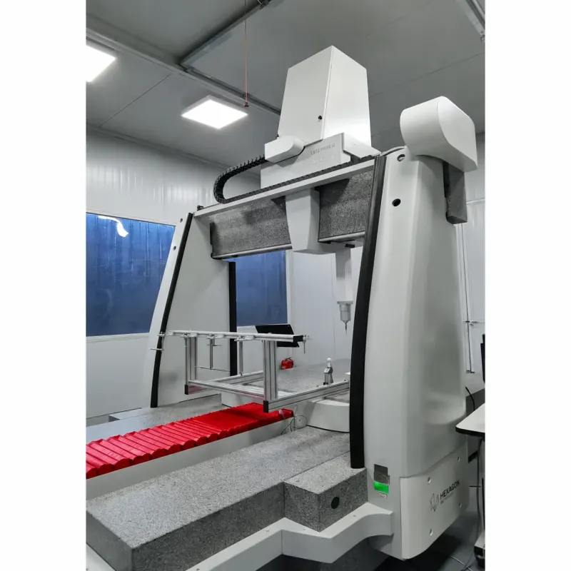
DieStrike builds these tools in the mold room: plus or minus 0.005 mm mold tolerance with plus or minus 0.002 mm on EDM and jig grinding, HRC 62 maximum heat treatment, 120+ machines under an IATF 16949 quality system, standard components in 3 to 7 days and tool lead times of 2 to 5 weeks, with tier-1 references including TE, Amphenol, Luxshare and Dongshan. We tool it; the plating and molding downstream run on the molder you buy from and your plater's lines. Send the part print, the witness agreement and the plater's spec into a DFM review, and the tool starts from the plating map rather than a guess.
KEEP READING
Related Reading
How to Control Gate Vestige and Cosmetic Quality on Class A Parts
Vestige height, gate land and wash-out rules for surfaces a customer inspects head-on.
Read articleArticleABS Injection Molding: The Complete Material Guide
The plating-grade rubber-phase resin: drying, mold temperature, shrinkage and gloss windows.
Read articleArticleEDM Surface Finish vs SPI Texture: How to Specify Both
What the EDM white layer costs you when a face later gets mirror polished to SPI A1.
Read articleServiceMold Design and DFM
IATF 16949 design reviews that fix gate witness, vent depth and stress limits before cutting steel.
Read articleNEXT STEP
Ready to Start Your Mold?
Send us your element dimensions or part numbers — our team responds within 24 hours. Pricing and lead time come with the answer.

Written by
Ray ChanExport Brand Manager at DieStrike. Ray helps global importers, distributors and OEMs source factory-direct molds and mold parts.