
How to Design Squeeze Casting Dies: Pressure, Feed and Microstructure
Table of Contents
A squeeze casting die that gets pressure too late locks cold shuts inside a sound-looking skin. The part passes visual and the first X-ray film. It then cracks at the fillet on a 500 N fatigue screen, and the line stops at the foundry you send it to. On a 6 to 20 kg bracket that miss costs a re-cut and a requalification run, because T6 heat treat assumed a weldable, radiographic-clean casting. This guide sets out the die-side numbers for squeeze casting, the slow-plunger process that feeds solidification instead of filling.
Everything below is buyer-side and shop-floor guidance for direct and indirect squeeze dies, verified against the alloy datasheet and the press.
The Snapshot
- 50 to 150 MPa held for 30 to 120 s. Pressure lands 1 to 5 s after plunger contact and stays on until the part is solid. A 25 mm wall needs 45 to 90 s of hold.
- Porosity under CT4 on X-ray. No high-velocity jet means no entrainment air. Elongation on Al 356 squeeze parts runs 4 to 10 percent against 1 to 3 percent on HPDC, so T6 heat treat and welding become options.
- The plunger bore is the wear pair. A soft bore grows 0.1 to 0.3 mm oversize in 5,000 to 20,000 shots. H13 at 46 to 52 HRC with a 600 to 700 HV nitrided case on the bore is the fix, quoted as a wear part.
- Tooling at 1.2 to 2x a gravity die, 0.4 to 0.6x a vacuum HPDC die. Die life runs 30,000 to 120,000 shots with cycles of 60 to 180 s on 6 to 20 kg parts.
What Squeeze Casting Actually Does
Squeeze casting, also called liquid die stamping, starts with a poured shot, not a jetted one. The foundry ladles melt 10 to 30 percent above the cavity volume into an open or nearly open die. A hardened steel plunger closes the bore. The press then drives 50 to 150 MPa into the liquid through that plunger while the part freezes.
Fill speed is the whole difference. HPDC pushes metal at 30 to 60 m/s through a gate and traps air doing it. Squeeze pushes metal at 0.05 to 0.5 m/s, a laminar creep that leaves almost no entrainment porosity. The shrinkage that would become bubbles in a jet gets fed instead. A hydrostatic head of 50 to 150 MPa holds until the last liquid island solidifies.
The payoff shows up in three measurable places. Structural squeeze parts hold X-ray films under CT4, a porosity class HPDC rarely reaches without vacuum assistance. Elongation on T6 Al 356 squeeze parts runs 4 to 10 percent against 1 to 3 percent on HPDC of the same alloy. Iron pickup stays low and the oxide film stays thin. The parts therefore weld and heat treat without the blistering that condemns HPDC castings to as-cast or T5 conditions.

The cost of that soundness is time. Pressure has to stay up while the part freezes, so cycles run 60 to 180 s instead of the 15 to 40 s of HPDC. One pour, one squeeze, one cooling wait: squeeze casting trades output for a casting you can treat, weld and radiograph.
Direct Versus Indirect: Where the Seal Sits
Two machine families carry the process, and the die looks different under each because the pressure seal lives in a different place. Direct squeeze puts the plunger on the melt surface. Pressure travels through a steel face sitting in a bore that is also the last gate. The plunger diameter equals the bore diameter, so there is no separate feed path to design. The cavity sits under an open pour, usually on the fixed half of a vertical press.
Indirect squeeze, the Boley variant, keeps the plunger away from the cavity. A piston pressurizes a small shot chamber, and metal feeds the cavity through a sprue that acts as an intensification chamber. Here the die must seal pressure in the sprue, not on the melt surface, and the geometry of that sprue decides whether feeding works.
Three die decisions follow from the split. Direct dies draft the plunger bore 0.5 to 1 degree so the part and stub release on ejector travel. Indirect dies size the sprue at 1.2 to 2 times the gate area so it stays liquid longest and feeds last. The pressure seal, whether a plunger-to-bore line or a sprue freeze joint, is the wear feature worth quoting as a replaceable insert on both families.
Where HPDC families split on the machine, not the die, see the comparison of hot chamber versus cold chamber die casting. Squeeze splits on the die itself, so the choice belongs in the print review, before any steel is ordered.
Die Steel, Hardness and the Wear Pair
The die body is H13, vacuum-hardened and tempered to 46 to 52 HRC. That window is deliberate. Harder steel cracks under the thermal swing of a poured shot. Softer steel flows under a 100 to 150 MPa static head held a minute at a time. Cavity half, core half and plunger bore all start from the same vacuum heat-treated bar.
The bore is the number to watch. A soft or unhardened plunger bore grows 0.1 to 0.3 mm oversize within 5,000 to 20,000 shots. The aluminum abrades it and the pressure hammers it. Once bore-to-plunger clearance passes about 0.15 mm, metal squirts up the gap, squeeze pressure drops below spec, and flash climbs the stub.
Bore and plunger are therefore a matched wear pair. Quote the plunger as a consumable, and cut the bore as a replaceable bushed insert where the die budget allows.
Nitriding protects both faces. A 600 to 700 HV compound case, roughly 0.10 to 0.20 mm deep, on bore and plunger raises abrasion resistance. It avoids the brittleness of a full-hard 58 HRC die. High-wear bores get the case; the cavity face usually stays at the 46 to 52 HRC base so thermal fatigue resistance survives. The full steel decision tree, including P20 versus H13 versus S136 for hot work, sits in selecting mold steel for die casting dies.
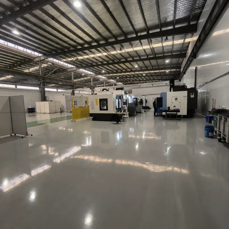
Hardness alone will not save a die that is cut wrong. Cut bore and plunger from one matched batch and grind the bore to plus or minus 0.02 mm. Put the wear allowance in the die as a bush, so a field re-bore is a 2-hour insert swap instead of a die pull. We make the die with that insert architecture as standard on squeeze work. The foundry you send it to then replaces the pair at a scheduled shot count, not at a breakdown.
The Feed System Without a Biscuit
Indirect squeeze feeds through a sprue, and the sprue is the gate, the intensifier and the timer at once. Size the sprue cross-section at 1.2 to 2 times the gate area so it freezes last and keeps the cavity under pressure while the part solidifies. A sprue that freezes first turns the squeeze into a gravity pour with a stamp on top.
The biscuit changes character. On HPDC the biscuit is 20 to 35 percent of the shot and it ejects with a bang at the end of fill. On indirect squeeze it runs 5 to 15 percent of the shot. It is the residue of the intensification chamber and stays under load until the hold timer ends. Design it as a stub pulled with the part, then trimmed, not as a runner fragment broken off in the cavity.
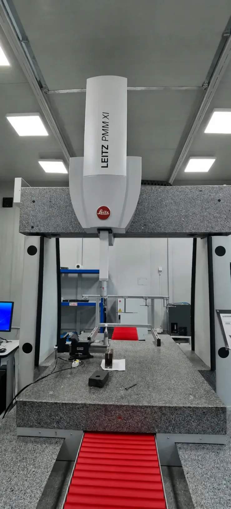
Oxide skins are the other thing the feed has to catch. Slow filling still pushes surface oxide ahead of the last metal in. An overflow well at the end of fill takes the skins the pressure drove forward. Do not put overflows at the vents. Squeeze pressure closes vent paths flat, and a vent-side overflow becomes a cold iron trap, not a debris collector.
Vents still exist where pressure is off. Run them 0.10 to 0.20 mm deep and 6 to 15 mm wide, landed on the fixed half at the last-to-fill corners. Keep them out of the pressurized seal line. On direct squeeze the bore wall is the gate geometry, so draft the bore 0.5 to 1 degree toward ejector travel. The pour opening vents trapped air before the plunger seats.
Pressure Timing and Sump Geometry
The press cycle is a race against the freeze. Die preheat runs 250 to 350 C before the first shot and stays in that band through production. Monitor it at the cavity face with a contact pyrometer. Aluminum 356 and 319 melt arrives at 660 to 700 C. That 300 to 400 C drop means a skin starts freezing the second the pour touches the steel.
Pressure has to land while the metal is still mostly liquid. Bring the plunger to contact, then reach full pressure within 1 to 5 s. Ramp that pressure over 0.3 to 1.0 s to avoid splash-up through the pour opening. Hold 50 to 150 MPa until the last liquid island freezes.
Hold time is wall thickness, not guesswork. A 25 mm wall needs 45 to 90 s. The whole cycle lands at 60 to 180 s with load, pour, squeeze and cool inside it.
Miss the window and the die cannot fix it later. If pressure arrives after the pool is 60 to 70 percent solid, the remaining liquid islands close into cold shuts locked under load. The film looks clean, and the part fails a fatigue screen or a CT-class X-ray at the foundry you send it to. The fix is upstream: thicker boil reserve, faster plunger advance, or a hotter die face within the 250 to 350 C band.
Boil geometry is the reserve that makes the timing honest. On direct dies the pour leaves 10 to 30 percent extra volume above cavity. The sump under the plunger keeps 5 to 10 mm of liquid metal against the plunger face for the full hold, so it squeezes metal rather than air. On indirect dies the sprue and chamber carry that reserve together, and the intensification pin needs visible stroke margin at hold end, not a bottomed-out ram.
Graphite Coatings Under Static Load
Squeeze dies run graphite-based die coatings, not the water-borne release sprays that HPDC dies live on. The coat is a 25 to 50 µm graphite film baked onto the working face at about 200 C. Rebuild it by spray every 10 to 40 shots depending on part area. It carries the static load, insulates the steel, and lets the casting release.
Both failure directions come from coat thickness. Too thick a coat burns back during the hold. The gas it releases lands as subsurface porosity in the last-to-freeze boss. Too thin a coat exposes bare steel, and aluminum soldering starts within a few hundred shots at the core pins and bore edge. Soldering is the weld-on of casting skin to die face under 100 MPa of static head. Keep the dilution ratio, spray volume and pulse timing from setting die spray and release agent, and log the rebuild interval on the shot counter.
Cooling and Heat Balance
There is no high-speed fill to dump heat across the die, so squeeze cooling is conduction work. Run internal pipes 30 to 60 mm from the working face on the ejector half. Baffle or bubble the deep core pins where the wall mass sits longest. The face must enter each shot inside the 250 to 350 C band and leave the hold before the boil freezes short of the plunger face.
Between shots, allow 15 to 25 s of spray and air cool on the open die, timed with the pour. That window is also where a hot core pin shows itself. Thermal fatigue cracking 0.05 to 0.15 mm deep appears on an unprotected core face after 20,000 to 60,000 shots. Nitriding plus a 45 to 48 HRC base roughly doubles that life. The circuit layout that buys those seconds lives in die casting die cooling design.

Balance is a measurement, not a belief. Put thermocouple holes or use a contact pyrometer at 6 to 10 named points on each face. Record the spread at steady state and accept nothing wider than about 40 C across the cavity. A die that runs 80 C hotter on one rib will solder, crack and shrink out of tolerance on that rib first.
Ejection: When the Part Shrinks on the Core
Squeeze parts grip the steel differently than HPDC parts. Under 50 to 150 MPa of hold the casting conforms to every core surface. It then shrinks onto the pins as it cools. Aluminum alloy 356 pulls roughly 6 to 7 per cent linear shrinkage, and a held part welds-tight to core pins it never touches in a high-pressure die. Plan ejection before the first cut.
Run 3 to 5 degrees of draft minimum on every cored surface, measured on the draw direction of the movable half. A 100 mm deep core at 3 degrees releases with about 5 mm of side relief; anything steeper sticks, galls or tears on the strip. Keep ejector pins away from the plunger bore. A pin scoring the bore wall opens the 0.02 to 0.05 mm clearance that kills squeeze pressure. Where geometry forces a pin near the bore, use stepped pins shoulding below the bore line, or carry the load on a stripper plate around the stub.

The sprue stub on direct dies returns with the plunger. When the plunger retracts, the frozen stub either follows the punch side or clings to the bore. Put a knock-pin on the open side of the bore face and size its land for the 5 to 15 mm stub section. On indirect dies the stub breaks at the biscuit line into the fixed half. Give it its own ejector sleeve around the sprue, sized 1.2 times the sprue diameter so the sheared skin cannot jam.
Part Design Rules for Squeeze
The process feeds liquid, so the print has to give it a path. Walls run 4 to 10 mm typical. Below 3 mm the pressure front stalls, and the wall never sees feed metal. That shows up as distributed micro porosity in the CT film. Above 20 mm the hold time stretches past 120 s and the cycle loses money, so thick zones get cored out or moved to a boss.
Bosses and ribs that need local feeding get squeezed through a second small plunger. A 25 mm mounting boss on a bracket can carry its own 40 mm bore and pressure pin on the fixed half, applied with the main stroke. Radii start at R2 on every internal corner. Squeeze metal will not fill a sharp V the way a jet does. The corner is where the fatigue crack starts at 4 to 10 per cent elongation anyway.
Undercuts are off the menu where pressure seals live. A slide interface inside the pressurized envelope leaks at the mating face, the same way a soft bore does. Design away from slides: core from the parting line, put snap features in the machining envelope, or machine the undercut after trim. The parting line follows the same rule. Hold the seal line on the fixed half where possible, and keep it off cosmetic surfaces.
Failure Modes and X-Ray Acceptance
Read defects by sequence, because squeeze has one signature failure chain: late pressure, locked shrinkage, rejected film. The table below pairs each mode with the die-side number that prevents it.
| Failure mode | Die-side cause | Control number |
|---|---|---|
| Cold shuts locked under load | Pressure applied after 60 to 70 per cent solid fraction | Contact to full pressure in 1 to 5 s, rise ramp 0.3 to 1.0 s |
| Shrinkage cavity at the last boss | Sprue froze before the part; no feed reserve left | Sprue area 1.2 to 2x gate; hold 45 to 90 s on 25 mm wall |
| Gas porosity under the skin | Coating too thick, burn gas pulled under the squeeze front | Graphite film 25 to 50 µm, baked at 200 C, re-spray every 10 to 40 shots |
| Soldered cavity face | Coat too thin, aluminum welded to bare H13 under static load | Nitride high-wear faces 600 to 700 HV, log rebuild on shot counter |
| Pressure decay mid-hold | Plunger bore worn oversize, metal squirts the gap | Replace bore plus plunger at 0.15 mm clearance growth |
| Thermal fatigue cracking on cores | Hot core pin cycling above the coating window | Cracks reach 0.05 to 0.15 mm by 20 to 60k shots; nitriding roughly doubles life |
| Torn cored boss on ejection | Draft under 3 degrees, pin load on a shrink-gripped core | Draft 3 to 5 degrees, stepped pins or stripper plate at the bore |
← swipe to scroll →
Table note: timings, clearances and shot counts are typical industry values for aluminum 356 and 319 squeeze work. Confirm them against the alloy datasheet, the press curve and the foundry CT class before a die is cut.
Acceptance belongs on the print, not in a handshake. Write the radiographic class on the order, CT4 or tighter for structural squeeze parts per the foundry class sheet. Add the T6 condition and an elongation floor of 4 per cent on a coupon cast with the part. State the X-ray film count per lot before the die is released.
When Squeeze Wins and When It Does Not
Squeeze wins when the part must be heat-treated, welded or radiographic-clean at 6 to 20 kg. Control-arm bodies, steering brackets, knuckle housings and EV battery cross-members live there. Those parts need the 4 to 10 per cent elongation and CT100 film that only a fed solidification can give. The 1.2 to 2x gravity-die tooling cost is small next to a scrap-driven recall.
It loses when volume rules. Vacuum-assisted HPDC prints similar brackets at two to three times the output on a 20 to 40 s cycle. That works if the design accepts as-cast or T5 properties and a CT4-class film. LPDC owns the big thin parts, 1 to 4 mm walls across a wide envelope, that a squeeze bore cannot cover evenly. Gravity dies still own low-volume, non-structural castings where 2 to 3 per cent elongation is enough.
Decide on three numbers, in order. First, the required elongation or heat-treat class. Second, monthly volume against the 60 to 180 s squeeze cycle. Third, part mass inside the 6 to 20 kg window the presses feed well. Squeeze casting sits between the low-pressure and HPDC families on almost every chart, and routing narrows process by process from there.
Squeeze Die Design Checklist
Run this list against the die drawing before steel is bought. Every line is a number a reviewer should read off the print, not off the press.
- Route and seal location. Direct or indirect stated on the drawing, with the pressure seal face drawn, drafted 0.5 to 1 degree on direct bores.
- Steel and case. H13 vacuum-hardened 46 to 52 HRC, bore and plunger nitrided 600 to 700 HV, wear pair quoted with a 0.15 mm replacement limit.
- Feed sizing. Sprue 1.2 to 2x gate area, overflow well at end of fill, biscuit held to 5 to 15 per cent of shot, vents 0.10 to 0.20 mm deep only where pressure is off.
- Timing window. Die preheat 250 to 350 C, melt 660 to 700 C, contact-to-pressure 1 to 5 s, hold 30 to 120 s mapped to the thickest wall.
- Coat plan. Graphite 25 to 50 µm baked film, rebuild every 10 to 40 shots, dilution and spray pulses logged on the process sheet.
- Heat balance. Pipes 30 to 60 mm from face, baffled deep pins, 6 to 10 pyrometer points, face spread under 40 C, 15 to 25 s inter-shot cool.
- Ejection plan. Draft 3 to 5 degrees, stepped pins or stripper at the bore, knock-pin for the returned stub, sleeve at 1.2x sprue diameter.
- Acceptance paper. CT class, T6 condition, 4 per cent elongation coupon, film count per lot, die-life target of 30 to 120k shots written into the order.
The Bottom Line
Squeeze casting die design is a timing and sealing problem wearing a stamping-die body. Hold the process to its numbers and the parts come out feedable. Run 50 to 150 MPa applied 1 to 5 s after plunger contact and held 30 to 120 s. Keep the die at 250 to 350 C under 660 to 700 C melt.
The wear and feed rules close the loop. Replace the nitrided H13 bore-and-plunger pair at 0.15 mm of wear. Keep graphite coats at 25 to 50 µm. Size sprues at 1.2 to 2 times gate area. Keep vents at 0.10 to 0.20 mm deep, and the die holds its CT class for life.
DieStrike tools this steel inside an IATF 16949 quality system. Die work runs to plus or minus 0.005 mm, EDM and jig grinding to plus or minus 0.002 mm. Hardness reaches HRC 62 where the process needs it, on 120+ machines. Standard components ship in 3 to 7 days and tool lead times run 2 to 5 weeks. Tier-1 references include TE, Amphenol, Luxshare and Dongshan.
Squeeze die work runs through our die casting mold service.
KEEP READING
Related Reading
How to Select Mold Steel for Die Casting Dies
H13, nitriding and hardness windows for aluminum and magnesium die casting tool steels.
Read articleArticleHow to Set Die Spray and Release Agent
Dilution ratios, spray volume and pulse timing that keep a casting die coating at working thickness.
Read articleServiceDie Casting Mold Manufacturing
IATF 16949 die work to plus or minus 0.005 mm, with bores and plungers ground as matched wear pairs.
Read articleIndustryAutomotive Die Casting Parts
Heat-treatable structural castings such as brackets and arms, built against CT-class x-ray limits.
Read articleNEXT STEP
Ready to Start Your Mold?
Send us your element dimensions or part numbers — our team responds within 24 hours. Pricing and lead time come with the answer.

Written by
Ray ChanExport Brand Manager at DieStrike. Ray helps global importers, distributors and OEMs source factory-direct molds and mold parts.