
How to Set Up a Mold on an Injection Press: Rigging to First Shot
Table of Contents
A setup crew that skips the paperwork on a 1,400 kg connector tool pays for it twice. The first bill arrives when a clamp closes without low-pressure protection set and cracks a 0.005 mm matched core. That repair runs 5 to 10 working days on a hardened insert. The second bill is the press itself: a two-hour setup that turns into a twelve-hour outage on a 3,000 part per hour cell costs more production time than most molds cost to build. This guide sets out the two-hour sequence from mold arrival to first good shot, with one number to record at every step.
The scope is a horizontal hydraulic or electric press in your molding cell, a mold coming off the rack or off our truck from the tooling shop, and a two-person setup crew working to a written SOP.
The Snapshot
- Rigging to first shot in about 2 hours. Paperwork 20 minutes, lift and set 30 minutes, clamp and hook-ups 40 minutes, soak and first shots 30 minutes, then the process card.
- Clamp tonnage checked before the crane moves. Production presses run 300 to 1,500 kN, and the mold needs projected area at 300 to 500 bar cavity pressure plus 10 to 20 percent for the runner.
- Low-pressure mold protection at 20 to 40 kN with a 1 to 2 mm safety gap. A clamp that closes past 40 kN on a shut-off finds an obstruction, not a parting line.
- Shot weight CV under 0.5 percent over 25 shots. Cushion held at 2 to 5 mm and a V to P changeover at 95 to 98 percent fill are the two dials that get the cell there.
The Two-Hour Window
Setup is a sequence, not a scramble. Each block below ends with a check that fails forward: the crew reads a number, records it, and only then moves on. A crew that starts the lift at minute zero finishes the first good shot at minute 110 to 125, assuming the mold arrives with its passport and the press is idle and clean.
Minute 0 to 20 is paperwork and press capability. Minute 20 to 50 is the lift, the set and the centering checks. Minute 50 to 90 is clamping, water, hydraulics and electrical hook-ups. Minute 90 to 120 is the dry cycle, the soak and the short-shot study. The process card and the handover signature close the window.
The three numbers the crew should never negotiate are the mold protection setting, the lift point rule and the shot weight CV. A mold that survives all three will still produce bad parts if the process is wrong, but no number on a process card fixes a cracked shut-off or a dropped tool.
The Mold Passport
The mold passport is the one-page data sheet that travels with the tool, and the setup crew reads it before the crane leaves the rack. It carries the as-built numbers, not the design estimates: actual weight with the mounting plates, shut height, daylight opening, sprue bushing diameter and taper angle, and ejector stroke. It also carries the cooling circuit map with zone labels, the hot-runner zone table with thermocouple types if the tool has one, the cavity count, and the process sheet from the last run that held tolerance.
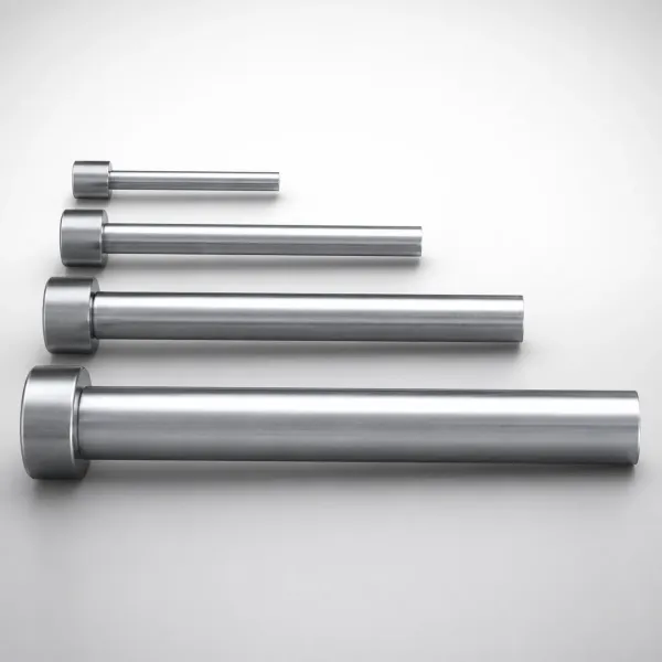
Two of those fields kill setups most often. A crew that ignores shut height can float the clamp past the press limit and crush the tie-bar lock. Ignoring ejector stroke is worse: over-travel bends an ejector pin on the first ejection. The ejector pin mistakes guide catalogues that failure.
| Passport field | Number to read | What skipping it costs |
|---|---|---|
| Mold weight | Actual kg on the hook, not the drawing mass | A sling rated under the load fails at the first lift |
| Shut height and daylight | mm, plus 20 to 30 percent of daylight as the minimum opening | Clamp floats past the press limit and strips the tie-bar lock |
| Sprue bushing diameter and taper | mm bore, 2 to 4 degree taper, matched to the nozzle | A mismatched nozzle shears the bushing or sticks the sprue |
| Ejector stroke | mm of travel the press knock-out can deliver | Over-travel bends pins; under-travel leaves parts stuck |
| Circuit map and zone table | Circuit order, series or parallel, zone count | Cross-connected hoses overheat one half in 10 cycles |
| Last process sheet | Cycle time, cushion, hold pressure that held tolerance | The crew re-derives a proven process from zero |
← swipe to scroll →
Table note: passport fields and bands are typical for production injection molds between 200 kg and 3,000 kg. Confirm every number against the as-built tool file the mold maker ships with the tool.
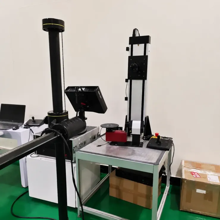
If the passport is missing, the setup does not start. The crew photographs the mold data plate, calls the molder's tooling file or the shop that cut the tool, and rebuilds the sheet before the crane is hooked. This is the same discipline a buyer-side acceptance checklist enforces at receiving, and a mold we hand over carries these fields stamped or printed on the data plate, with ±0.005 mm dimensional records in the tool file.
Checking the Press Can Hold the Mold
The crew proves the press fits the mold on four lines before the crane moves. Clamp tonnage comes first. Multiply the projected cavity and runner area by the cavity pressure the fill needs, typically 300 to 500 bar on the part plus 10 to 20 percent on the runner. That product has to land inside the press rating, and production hydraulic presses cover 300 to 1,500 kN.
Tie-bar spacing has to clear the mold width on all four sides, and the platen hole pattern has to match the mold foot. Platens are drilled on a 100 to 200 mm grid, so a mold with 220 mm foot centers either gets adapter plates on a 40 mm minimum overlap or does not get mounted at all. Mold height comes next. Shut height has to sit inside the press die-height range, and daylight opening has to exceed mold height plus 20 to 30 percent so the parts and the sprue drop clear.
Shot size closes the check. Part plus runner weight at 80 percent of the barrel maximum shot keeps the screw inside its window. A press where the shot runs under 20 percent of barrel capacity cannot hold a cushion. If any line fails, the mold goes to a different cell; nothing on a setup sheet fixes a tonnage deficit. The full compatibility matrix sits in the mold to machine compatibility checklist.
Rigging and Lifting Discipline
A 2,000 kg tool falls for the same reason every time: the hook went somewhere other than the four lifting holes. Mold lifting holes are engineered into the clamp plates, positioned so the tool hangs level, and rated with a margin. A side lift, a latch or a hydraulic cylinder is not a lift point and bends or shears under the load. The crew uses the mold's own holes, with eyebolts whose thread engagement is at least 1.5 times the bolt diameter, screwed home until the shoulder seats.
The sling angle carries the real load. A four-point bridle at 60 degrees from vertical puts about 1.15 times the quarter weight into each leg; at 30 degrees from vertical that multiplier reaches 2 times, so a bridle laid flat is a bridle overloaded. Level the tool with the adjustable rigging screws before it leaves the rack, and keep the first lift 300 mm off the floor long enough to confirm the balance.
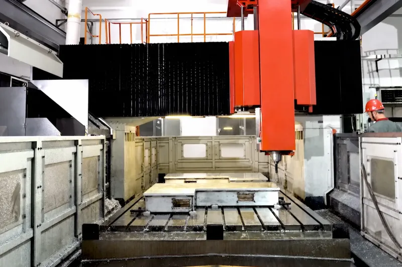
Transport is slow travel, never a swing. The mold moves over the press platen in a straight drop line with a spotter on each tag line, and the crane stops the instant anyone calls it. Approaching the platen, the crew tilts the tool to the working orientation and opens the halves slowly with a guide-bar spreader so the moving half cannot drop off its barrel wedges and swing on the crane hook. A mold half that swings on one guide bar bends it; a 0.1 mm bent bar is a mold that will not close parallel.
Set the mold centered before a single bolt goes in. The ejector centerline has to land within 2 mm of the press knock-out center, and the sprue bushing has to sit concentric with the nozzle within 0.5 mm. The crew checks both with a straightedge and a center mark on the platen, then confirms the clamp plates rest flat with 0.05 mm feeler gauges at four corners before the first bolt is torqued.
Centering, Clamping and Mold Protection
Clamp bolts go in a crisscross pattern at 60 to 80 percent of preload on the first pass, then full value on the second. M12 and M16 high-tensile grade 10.9 bolts carry roughly 40 to 60 Nm per 100 mm of mold support span, and the rule is four bolts minimum per clamp plate, sized for the shear load of the tonnage, not the convenience of the socket. Support blocks go under any cantilever plate so the mold base does not flex 0.1 mm at full clamp pressure.
Then the number that saves the tool: low-pressure mold protection. The crew sets the cushion close so the halves meet at 20 to 40 kN with a 1 to 2 mm safety gap before the tonnage circuit engages. Set the protection stroke stop so the clamp reverses on contact. A clamp that closes past 40 kN onto an obstruction is not molding, it is a press. Every mold over 1,000 kN should run with protection enabled; running full tonnage with protection off is one of the ten mistakes listed later in this guide.

Test the close on paper before plastic. A strip of printer paper across two shut-offs, clamped at protection pressure, should grip a 0.05 mm feeler on withdrawal, and the paper drag should read even along the land. Then check the parallel with the feeler at all four corners at full tonnage: a spread over 0.05 mm across a 500 mm platen means the mold is sitting on debris or a lifted bolt, and flash on one side of the first cavity will confirm it in ten shots.
Manual actions get parked and tied before the first close. Every lifter, slide and unscrewing actuator has a park position, and the crew confirms each one travels free by hand. Set the press sequence so the mold protection sees a hard stop at the wrong position, and never cycle a tool with a slide parked against the clamp. Crushing a slide home at 800 kN shears the wedge face, and that insert repair takes the tool out of the cell for a week.
Water, Hydraulic and Electrical Hook-Ups
Water lines get blown out for 30 seconds before any hose touches a mold fitting. Shop lines carry swarf, scale and the ghost of the last tool's coolant, and one 0.5 mm chip in a 8 mm baffle seals a circuit from the inside. The crew matches circuit order to the mold map, series or parallel exactly as the cooling design states, and labels every line at both ends. On a 12-zone tool, an unlabelled hose bank is how a first run overheats the core while the cavity freezes.
The flow targets: an 8 to 14 degree Celsius delta across the mold, 2 to 4 bar working pressure at the manifold, and turbulent flow in each circuit. Torque hose clamps or quick-tight couplings to 60 Nm, so a 90 degree C return line does not spit a fitting across the cell on the first hot cycle. Water temperature controllers run the mold half setpoints, and the crew records each circuit's delta at the meter before the first shot, not after.
Hydraulics come second. Hydraulic core pulls and lifters get their sequence valve opening pressure set per the mold document. Purge air from the lines by cycling each cylinder slowly three times, and confirm the relief valve at the mold's rated pressure, typically 70 to 140 bar on mold-side cylinders. A lifter that fires late against the closing halves is the crush-incident the slide-parking rule exists to prevent.
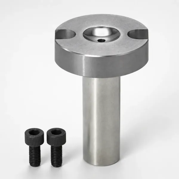
Electrical is the last hook-up and the one with the most expensive shortcut. Heater bands run 208 or 480 V, thermocouples are type K or J, and the hot-runner controller ramps at 25 to 40 degrees Celsius per hour to setpoint. A cold-start full-voltage dump into a 380 V manifold blows an element in 3 to 10 cycles. Before power-up, verify heater continuity at 10 to 40 ohm per zone. Check each thermocouple against a handheld at ambient, and confirm the controller error stays inside plus or minus 5 degrees Celsius on every zone before the soak clock starts.
Nozzle and Screw Interface
The nozzle meets the sprue bushing with force measured in percent, not feel. Nozzle contact force gets set at 1 to 3 percent of clamp tonnage, enough to seal a sprue without bridling the bushing. A crew that jams the nozzle home by hand-wrench pressure deforms the bushing entry, and a deformed entry leaks melt at the parting line by the hundredth shot.
Dry cycle first, plastic second. The crew runs the mold open and closed 10 to 20 times with no plastic, watching ejection, lifter park and sprue pull on every cycle. The sprue puller stroke gets set at 5 to 10 mm, enough to strip the sprue from the A-half with the runner. Then a purge-only shot: clear compound pushed through to confirm the nozzle seals and the gate flow starts.
Read the witness ring on the sprue bushing face after the purge. A bright concentric ring means the nozzle seals on the bushing, which is the correct interface. No ring means the nozzle is sealing on the parting line of the A-plate, a condition that welds nozzle to bushing within a hot shift and scores the plate face.
The screw settings that start a setup are not the settings that finish it. Melt temperature goes to the resin datasheet window, back pressure to the low band that still mixes color, and screw recovery to a cushion of 2 to 5 mm. On a hot-runner tool, valve-gate timing and nozzle temperatures come from the commissioning record the mold maker ships with the tool. A hot tip that runs without thermocouple control is banned at this step, not at the trial.
Soak, Short Shots and the Process Card
Mold to setpoint, then soak 15 to 30 minutes before the fill study. Steel heats slower than the controller thinks: a cavity reading at temperature on the thermocouple can still be 10 degrees Celsius cold at the core face on a 600 kg block. The soak is why a short-shot study done at minute five lies to the crew.
The short-shot fill study runs 5 shots at 40, 60, 80, 95 and 100 percent fill, with the shot aborted before pack each time. The crew reads the fill map for balance across cavities, air traps at rib ends and last-fill corners, and weld-line positions where flows meet. On a 4-cavity tool, a fill balance over 3 percent between the lightest and heaviest short shot points at a gate or runner problem, not a process problem, and no cushion change will fix it.
Then the pack. The fill-to-pack changeover, V to P, gets set at 95 to 98 percent fill. Hold pressure and time go to the packing study window, and cooling time comes out of the thickness calculation, not the clock convenience. The crew passes the shot-weight gate before anyone touches a part: 25 consecutive shots inside plus or minus 0.3 to 0.5 percent CV. Skipping that gate ships dimensional drift into the next shift, and the reasoning behind it sits in the scientific molding study guide.
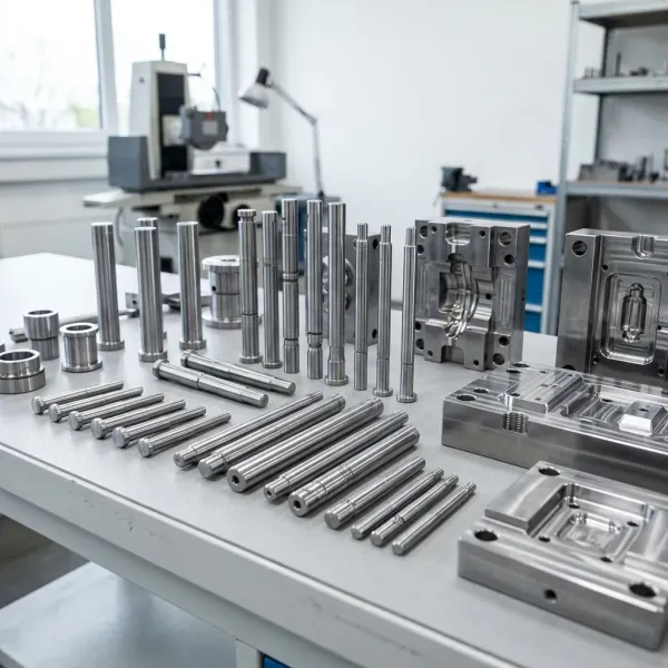
The process card closes the sequence. Every setpoint the study landed on, tonnage used, each zone temperature and its controller error, water sequence and delta, cushion, hold time and cycle time get written on the card and signed. The card is what the next shift sets up from, and a mold we tool and hand to your molding cell ships with a first-article process card that the crew can reproduce shot for shot.
Ten Rigging Mistakes That Damage Molds
Each mistake below costs shop hours or tool life, and each one has a number that proves it happened. They are listed in the order a crew can commit them across a setup.
| Mistake | Damage mechanism | Number that catches it |
|---|---|---|
| Crushing a slide or lifter with the clamp before checking its park | Sheared wedge face, cracked core block | Park position confirmed by hand before the first close |
| Ejecting against a manual pin left in the travel path | Bent ejector pin, scored plate bore | Pin count on and off the tool, 2 mm clearance check |
| Running a hot tip without thermocouple control | Element burnout, degraded gate freeze | Ramp 25 to 40 °C/h, continuity 10 to 40 ohm |
| Clamping on a sprue stuck in the A-half | Dished shut-off, crushed core | Protection at 20 to 40 kN reverses the clamp |
| Water at 90 °C into an epoxy-sealed circuit | Seal softens, cross-circuit leak | Circuit map states epoxy limit, typically 70 °C |
| An unbalanced 4-cavity fill forcing one gate 300 bar hot | Overpack, flash, weld-line crack on the fast cavity | Short-shot weight balance under 3 percent |
| Tightening a hot nozzle ring onto a cold barrel | Cross-threaded seat, leak at 150 bar injection | Torque at ambient, re-check after soak |
| Running to full tonnage with mold protection off | Every obstruction becomes a tool repair | Protection enabled and stroke stop verified |
| Crane-slamming the open halves | Bent guide bars, damaged wedges | Guide-bar spreader, 0.1 mm bar straightness |
| Leaving a copper wire or feeler on a shut-off | Witness groove pressed into polished steel | Paper-drag shut-off check before plastic |
← swipe to scroll →
Table note: mechanisms and limits are typical shop-floor values for production injection tooling. Confirm the protection stroke, temperature limits and balance targets against the mold document that ships with the tool.
Two rows repeat the same lesson from different angles. Mold protection at 20 to 40 kN catches the stuck sprue and the left-in pin because the clamp reverses before either becomes a crater. The paper-drag shut-off check catches the copper wire before the tonnage circuit ever presses it into a 0.02 mm groove on a polished cavity face.
Setup Record and Handover
A setup sheet gets stamped at handover, not remembered at the next changeover. It carries the clamp tonnage used, each zone temperature and its controller error, and the water sequence and delta per circuit. It also records first and last shot numbers of the setup run, cushion and hold time. Add every deviation from the process card, any mold damage found on inspection, a photo of the witness ring on the bushing, and the next maintenance due written in shots.
Deliverable, not paperwork. A setup the next shift can reproduce in two hours is the actual product of this SOP, and the deviation column is where the crew writes the truth about why the card was changed. Over six changeovers a year on a 12-cavity automotive tool, that record is the difference between a mold that runs to its 1,000,000 shot life and one that comes back to us for shut-off welding repair at 300,000.
The mold maker's side of the deal is the tool that makes this sequence short. A mold we cut under a mold design and DFM review and hand over arrives with the passport complete, lifting holes in the clamp plates, circuits labeled per the map, and a first-article process card the setup crew can load on the first pass. That is the two-hour setup, built in at the tooling stage.
The Bottom Line
A mold setup is a chain of numbers, and each one fails forward into the next. Read the passport, then prove the press fits: 300 to 1,500 kN of tonnage headroom, a 100 to 200 mm platen grid, and daylight 20 to 30 percent over mold height. Lift only the engineered holes at 1.5 diameters of thread engagement, and center within 2 mm on the ejector line and 0.5 mm on the bushing.
Close on the protection circuit first: 20 to 40 kN with a 1 to 2 mm gap, bolts torqued crisscross at 60 to 80 percent preload. Ramp hot runners at 25 to 40 °C/h, dry cycle 10 to 20 opens, and read the witness ring before the first real shot. Short-shot at 40 to 100 percent fill, then do not touch the parts until 25 shots hold CV under 0.5 percent.
DieStrike makes precision injection molds and dies under an IATF 16949 quality system, at ±0.005 mm mold tolerance, ±0.002 mm on EDM and jig grinding, HRC 62 maximum heat treatment, across 120+ machines, with tier-1 references including TE, Amphenol, Luxshare and Dongshan. Tool lead times run 2 to 5 weeks and standard components ship in 3 to 7 days. Explore the trial and T1 sampling service, or send the part print with your press data, and the mold that arrives at your cell sets up in the two hours this guide describes.
KEEP READING
Related Reading
How to Run a Mold Trial
The T1 acceptance sequence that follows a clean setup, with the readings and reports a trial should produce.
Read articleArticleHow to Match a Mold to an Injection Molding Machine
Clamp force, tie-bar spacing, platen hole pattern and shot size checks before a mold leaves the rack.
Read articleArticleHow to Build a Mold Acceptance Checklist
The acceptance lines a setup crew can reuse as the pre-arrival paperwork check.
Read articleServiceMold Trial and T1 Sampling
Tool tryout support on the molds we cut, with dimensional reports and process sheets returned to your molding cell.
Read articleNEXT STEP
Ready to Start Your Mold?
Send us your element dimensions or part numbers — our team responds within 24 hours. Pricing and lead time come with the answer.

Written by
Ray ChanExport Brand Manager at DieStrike. Ray helps global importers, distributors and OEMs source factory-direct molds and mold parts.