
How to Design Cold Heading Dies: Multistation Carbide Tooling
Table of Contents
A chipped entry chamfer stops a 6-blow header running at 800 parts per minute, and the wrong diagnosis costs more than the button. A bore worn 0.05 mm oversize on an 8 mm head flashes the part and locks the slug under the keeper. That station dies long before half of its 50,000 to 300,000 piece life. This guide sets the numbers behind multistation cold heading die design, from upset envelope to cost per thousand pieces.
Every figure below is a typical industry value for steel heading and needs checking against the wire certificate before a drawing is released.
The Snapshot
- Upset ratio 2.0 to 2.35 per blow. Mild steel reaches 3.0 in one blow, and multi-hit stations carry a 4 to 6 total upset on the same bolt.
- Carbide at 92 to 94 HRA runs 50,000 to 300,000 pieces. A tool steel die plastically deforms and fatigues at 1,000 to 5,000 pieces under the same load.
- Forming loads hit the die wall at 800 to 2000 MPa. Low-carbon wire flow stress runs 800 to 1200 MPa, so the die material is a pressure rating, not a hardness contest.
- Die seats ground to plus or minus 0.01 mm. Radial runout stays under 0.02 mm at 1200 parts per minute, because a wobbling station throws the whole head tolerance.
The Cold Heading Process Envelope
Cold heading upsets a cut blank of wire inside a closed die bore, at room temperature, in one or more punches. The governing ratio is h/D: blank length divided by the diameter of the section it is compressed into. Mild steel tolerates an upset ratio of 3.0 in a single blow, and most heading practice keeps each station between 2.0 and 2.35.
Above 2.35 the blank buckles instead of filling the corner. A buckled blank scraps the part or buries a cold shut inside the head. A total upset of 4 to 6 is still achievable, but only when pre-form dies split the work across two or three blows before the final form station. Multi-hit design beats a single-blow attempt over 2.4 upset every time, and that rule is drawn on the paper long before the die is cut.
The wire sets the load. Heading stock is low-carbon steel with 0.08 to 0.25 percent carbon, annealed or patent-rolled, in diameters from 2 to 30 mm. Flow stress in the die throat runs 800 to 1200 MPa, and peak contact pressure on the die wall reaches 800 to 2000 MPa during the form stroke.
Blank length is cut 5 to 15 percent over the volume the finished head needs. Under 5 percent the head fills short and the corner shows a cold shut. Over 15 percent the excess metal drives the upset ratio past 2.35, raises the forming load and flashes out through the wire clearance as a fin that the trim station has to remove.
Machine Families and Die Formats
Multi-blow headers come in 4-blow, 5-blow and 6-blow families, running 300 to 1,500 parts per minute. Each cycle follows the same sequence: cutoff, shear, forward or transfer to the next station, form, and pierce when the part needs a through hole. Every station is a small press with its own die pack and punch set, so the die work multiplies with the station count.
The die side of a header station is a three-piece stack. A ground die holder carries a carbide insert button at 12 to 16 mm diameter, a hardened retainer plate clamps the button from the top, and a keeper punch behind the button stops it being pushed out of the seat. The whole pack is replaceable in minutes, which is the point: the header shop changes wear parts, not the machine.
The punch side carries a shear punch for the cutoff, one or two pre-form punches, the form punch and, on coining stations, a flat-faced coining punch. Pre-form punches work at the lower end of the contact pressure band and can run in premium tool steel. The final form and coining punches see the full 800 to 2000 MPa and belong in carbide on any production quantity.
Two geometry numbers hold the machine honest. Die seats ground to plus or minus 0.01 mm keep each button concentric in its holder, and total radial runout of the pack stays under 0.02 mm at speeds up to 1200 parts per minute. A station running 0.05 mm of runout throws the head off-center, and the part maker reads that as a head concentricity failure, not a die problem.
Format choice follows part family. Rotary headers take the round button packs described above and own the bolt, screw and pin volume. Ask which die format the header shop carries before drawing a tool, because a button pack sized for a 6-blow rotary will not retrofit a competitor's station without new holders.
Carbide Grades Versus Tool Steel
Tungsten carbide carries the forming stations because nothing else survives the contact pressure. A WC-Co grade at 92 to 94 HRA holds its bore through 50,000 to 300,000 pieces. A through-hardened tool steel die, even at the HRC 62 ceiling our shop works to, plastically deforms and fatigues at 1,000 to 5,000 pieces under the same 800 to 2000 MPa load.
The cobalt binder phase is the tuning dial. Binder content runs 6 to 12 percent, and the trade is straight: more cobalt buys toughness against chipping, less cobalt buys wear resistance against bore growth. A deep, aggressive upset on a pre-form station wants the tougher 10 to 12 percent binder grade, while the final bore on a high-volume fastener wants the wear grade at the 94 HRA end.
Coatings close the galling gap. A polished carbide face can gall against brass-coated steel wire, and stainless picks up on bare carbide within a few thousand hits. A 0.5 to 2 micron TiC or DLC layer on the form faces raises the galling threshold and stretches the interval between crown polishes. Coating selection belongs on the drawing beside the grade, and the same pick-up logic is laid out for stamping tools in the die galling prevention guide.

Grade selection is a load read, not a hardness contest. Designers keep a 0.02 to 0.03 mm fracture-toughness margin at the bore for each step of upset ratio above 2.0, and they buy toughness before they buy wear life on short-run or multi-hit tools. The grind geometry, button sizing and fatigue margin behind that choice fill the carbide die component design guide.
| Die material | Hardness | Typical life | Where it belongs |
|---|---|---|---|
| Premium tool steel | Up to HRC 62 | 1,000 to 5,000 pieces | Shear and low-load pre-form stations, trials |
| WC-Co, 10 to 12 percent binder | 92 to 93 HRA | 50,000 to 150,000 pieces | Aggressive upsets, multi-hit pre-forms |
| WC-Co, low binder | 93 to 94 HRA | 150,000 to 300,000 pieces | Final form and coining bores, high volume |
| Coated carbide, 0.5 to 2 um TiC or DLC | 92 to 94 HRA base | 30 to 50 percent over uncoated on stainless | Stainless 302/304, aluminium 5052 to 6061, brass-coated wire |
← swipe to scroll →
Table note: hardness scales, life bands and coating gains are typical industry values for steel heading dies. Confirm the grade against the wire alloy, the upset ratio and the lube system before releasing the purchase order.
The material side has two named trouble cases. Stainless 302 and 304 heading needs a 12 to 15 percent extra die wear allowance plus a lime coating on the wire, and aluminium 5052 to 6061 galls polished carbide until you run DLC plus a kerosene-based lube. Both cases price into the button budget, not the die holder budget.
Die Pack and Retainer Geometry
The die pack is a floating assembly, and the float is engineered. The carbide button sits in the retainer with 0.02 to 0.05 mm vertical clearance so it can settle square under load instead of being pinched on one edge. A spring or urethane pad behind the button damps the shock of each hit and returns the pack to its seat between stations.
Stack height is the number that ties the pack to the machine. Set the stack so the die face meets the form punch at bottom dead center plus 0.1 to 0.2 mm of overlap. Short of that window the head fills under-height and the corner radii stay round; past it the punch crushes the button seat and the first failure you see is a chipped retainer edge.
The keeper punch is a sacrificial part with one job: stop the button walking out of its seat. It rides behind the pack through the holder, and it has to drop clear the instant the stroke reverses. A broken die button that plugs the bottom of the holder seizes the keeper in seconds, and that seizure is what cracks the holder bore, not the original chip.
Inspect the pack as an assembly, not as three parts. After every change, check button-to-retainer seating with a 0.02 mm feeler at four points and confirm the pack height against the stack drawing to plus or minus 0.01 mm. A pack that clamps with any tilt wears the bore oval, and an oval bore flashes the head on one side at exactly the wire clearance you thought you had.
Punch Side and Pierce Station Design
The pierce station is where slug physics decides whether your tool lives. Size the pierce punch with 1.5 to 2 degrees of draft along the barrel and run it with 0.05 mm clearance to the die bore so the slug has a channel to fall through. The slug must leave on every hit. A slug that drags one stroke doubles the pierce load in the next, and a doubled load is how a 12 to 16 mm button shatters without warning.
Two ejection routes keep the channel clear: a vacuum pickup at the die holder or an ejector pin fired through the holder behind the button. Pick one per station and write it into the die pack drawing, because both need their own maintenance interval and neither works if chips settle in the relief.
On the form side, the punch nose radius is the wear epicentre. Crater wear opens at the radius on the wire entry, and once the crater passes 0.05 mm across it copies itself onto every head crown that follows. Regrind the punch nose to the original radius profile rather than flattening it, and log hits per punch so the regrind interval matches the button interval on the same station.
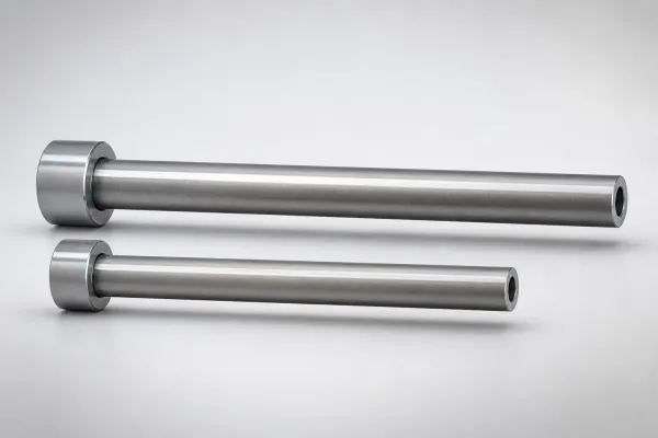
Guiding and shoulder design follow the same logic as any high-rate tooling: pilot the punch close, support the shank short and keep the head square to the bore within 0.02 mm. On transfer stations that push blanks between dies, ball-lock punch retainers earn their keep because shear loads hit the shoulder, not the retainer plate. For punch-side component choices, ball lock punches cover the retained designs and their load paths.
Lubrication and Wire Surface Condition
Cold heading lube is a coating decision made at the wire mill, not a spray decision made at the press. Standard carbon steel stock arrives phosphate plus soap slug-drawn, carrying 600 to 1500 mg per square metre of coating. Stainless runs a lime coating at 5 to 15 g per square metre because phosphate tears on a 2.35 upset. At the severe end, copper-plated wire at 12 to 25 micron replaces boundary lube entirely on high-ratio heads.
At the machine, a 60 to 100 cSt oil sprays every cycle, or a wick plus air mist carries a steadier film at lower flow. The lube system is part of the die design because it fixes the die temperature. Without enough film the die surface swings 100 to 300 C between hits, and that swing is the thermal fatigue crack starter that spalls an entry chamfer long before abrasive wear grows the bore.
Lube failure has a fast, legible signature. Galling pick-up appears within 50 to 200 pieces of the film breaking, and it scores the die crown before it does anything else. If a shop reports a crown scar, read the wire coil certificate and the spray pattern before you blame the carbide grade, because a coating at the 600 mg per square metre floor of the band will not hold a 2.3 upset on a 12 to 16 mm button. The wire certificate, the coating weight and the lube spec belong in the same tool file as the die drawing.
Tolerances and Inspection
The part tells you whether the die held its numbers. Head height is the first acceptance dimension, held to plus or minus 0.05 to 0.10 mm, and that band is set by die stack height and punch stroke, not by the header's controls. Under-head radius comes from the pre-form die profile, so a radius that reads sharp at the press means the pre-form station drifted, not the final form.
The shank side of the tool is a clearance game. Bore-to-punch running clearance on the form station sits in the 0.02 to 0.03 mm range, tight enough to size the shank, loose enough that the blank slides instead of scraping. Wire is the other half of that fit: measure stock diameter every coil against the certificate to 0.02 mm, because a 0.05 mm wire oversize overloads the form station and burns the upset allowance you designed into the blank length.
Inspect the die pack before it goes back on the machine. Seat the pack in the holder, run a 0.02 mm feeler at four points around the retainer, and read button concentricity on an optical comparator against the 0.02 mm runout limit. After a changeover, fire one station, cut the first head on a small-magnification scope, and check the crown and the corner fill against the print. A first-article sequence like this catches a tilted pack in one part instead of one coil.
Keep the inspection record with the tool file: die seat ground dimension, stack height measured, wire diameter logged per coil, first-article date and hits on the button. Under an IATF 16949 quality system that file is the traceability spine, and a die without it re-enters production as an unknown.
Die Failure Modes with Numbers
Cold heading dies fail in a short, named list. Chipping starts at the entry chamfer, where the blank's nose first touches steel. A 15 to 30 degree lead-in on the bore mouth spreads that contact; a square mouth concentrates it, and the first corner to chip takes the retainer and sometimes the holder with it.
Thermal fatigue is the second pattern, and it is a lubrication symptom wearing die clothing. A dry station swings the die surface 100 to 300 C between hits at 300 to 1,500 parts per minute, and that swing grows a crack network behind the bore until a flake spalls out. Crater wear at the punch nose radius is the third: it opens where the blank's lead edge first rubs, and the crater copies onto every crown after it.
| Failure | Where it starts | Number to check |
|---|---|---|
| Chipping at the bore mouth | Entry chamfer taking first blank contact | Lead-in 15 to 30 degrees, upset per blow under 2.35 |
| Thermal fatigue spalling | Die surface cycling hot and cold without film | Surface swing 100 to 300 C when lube fails, mist or spray every cycle |
| Crater wear at the nose | Blank lead edge rubbing the punch radius | Regrind at 0.05 mm crater, log hits per station |
| Oversize bore and flash | Blank sliding and burnishing the carbide wall | 0.05 mm wear on an 8 mm bore is 0.5 percent, and the slug locks |
| Keeper punch seizure | Broken button plugging the holder bottom | Stop station on any chipped fragment, clear seat to 0.02 mm feeler |
| Galling pick-up | Film breakdown on stainless or coated wire | Symptoms inside 50 to 200 pieces, coating 600 to 1500 mg per m2 |
← swipe to scroll →
Table note: the bands are typical for steel fastener heading on carbide tooling. Confirm the lead-in angle, wear limit and coating weight against your wire certificate and station speed before setting the regrind trigger.
The oversize bore row is the one buyers misprice. A die worn 0.05 mm on an 8 mm head bore flashes the head by roughly 0.5 percent and starts locking the header slug in the station. The plant reads it as a press problem for a week before anyone measures the bore, and the carbide that survives is already past its regrind window.
Die Life, Regrinds and Cost Math
Carbide buttons are consumables with a documented life, and the documentation is the money. Log hits per button on every station. Grind the carbide back when bore wear or crater depth reaches 0.05 to 0.10 mm, which buys two to five regrinds per button before the fatigue story ends.
Retirement is a crack decision, not a size decision. At 400x magnification, fatigue microcracks across the bore land mean the button is done, even if the dimension still prints green. Running a microcracked button is how a holder bore gets cracked on the next upset, and a holder is not a regrind item.
The cost structure rewards this discipline. A 6-blow header die set carries 25 to 60 standard pieces in holders, retainers and punches, plus 10 to 25 carbide buttons and punch noses cycling as wear parts on the machine. The number that actually competes with press time is die amortization, typically 1.5 to 8 USD per 1,000 pieces, and regrind service is what pulls that figure toward the floor. The same amortization logic for flat tooling is worked in the stamping die budget guide.
Buy the wear economy deliberately. A tougher carbide grade dies younger on wear but survives chipping on a marginal upset; a wear grade runs longer at stable loads. A coating at 0.5 to 2 microns buys galling headroom on stainless and aluminium at a per-button premium. Each of those choices moves the per-thousand figure, and the coil you scrap when you guess wrong moves it more.
Cold Heading Die Design Checklist
Run this list against the tool drawing before the die pack is cut. Each line carries the number a reviewer should read off the print, not off the press.
- Upset map per station. Show blank length, h/D per blow at 2.0 to 2.35, and the total upset split across pre-form and form stations.
- Grade and coating per button. State 92 to 94 HRA, binder 6 to 12 percent, and the 0.5 to 2 micron TiC or DLC callout on form faces.
- Entry chamfer. Lead-in drawn at 15 to 30 degrees on every bore mouth, with the regrind profile dimensioned.
- Die pack float and stack. 0.02 to 0.05 mm vertical clearance in the retainer, stack height bringing the die face to bottom dead center plus 0.1 to 0.2 mm.
- Pierce geometry. 1.5 to 2 degree punch draft, 0.05 mm clearance to the bore, and a named slug ejection route.
- Ground seats. Die seats to plus or minus 0.01 mm, pack runout under 0.02 mm at up to 1,200 parts per minute.
- Lube spec in the tool file. Wire coating weight (600 to 1500 mg per m2, or lime 5 to 15 g per m2), oil viscosity 60 to 100 cSt, application frequency.
- Life and retirement triggers. Hit log, regrind at 0.05 to 0.10 mm wear, scrap on 400x microcracking, amortization target 1.5 to 8 USD per 1,000 pieces.
A die that ships with its upset map, pack heights, lube spec and regrind triggers in one package is a die the next shop can run. The drawing is the contract; the numbers above are its clauses.
The Bottom Line
Cold heading die design is a wear economy priced in numbers. Hold each upset between 2.0 and 2.35 per blow, seat carbide at 92 to 94 HRA against 800 to 2000 MPa contact pressure, float the pack 0.02 to 0.05 mm in its retainer, and let 0.05 mm of bore wear ring the regrind alarm before the slug locks.
Wire and lube are part of the tool system, not shop consumables. A phosphate film at the 600 mg per m2 floor of the band will not carry a 2.35 upset, and a dry station cycling 100 to 300 C will spall a chamfer no grade can fix. Buy the die, the coating spec and the hit log together, and die amortization lands at 1.5 to 8 USD per 1,000 pieces instead of a scrapped holder.
DieStrike makes cold heading dies, carbide buttons and punch sets under an IATF 16949 quality system, with plus or minus 0.005 mm die accuracy, plus or minus 0.002 mm on EDM and jig grinding, HRC 62 on the steel components we heat treat, 120+ machines and DFM feedback on every part print. Standard components ship in 3 to 7 days and tool lead times run 2 to 5 weeks, with tier-1 references that include TE, Amphenol, Luxshare and Dongshan. The header shop keeps the presses; we keep the die pack honest. Send the part print, the upset map and the wire certificate through stamping die manufacturing and the tool starts from numbers instead of a coin flip.
KEEP READING
Related Reading
How to Design Carbide Die Components
Grade selection, grind geometry and fatigue margins for tungsten carbide die buttons and punches.
Read articleArticleHow to Prevent Stamping Die Galling
Coating, clearance and lubrication thresholds that stop adhesive pick-up inside 50 to 200 strikes.
Read articleArticleHow to Budget a Stamping Die
Where die set money goes: standard pieces, carbide wear parts and the regrind line item.
Read articleServiceStamping Die Manufacturing
IATF 16949 die work with plus or minus 0.005 mm accuracy and 2 to 5 week tool lead times.
Read articleNEXT STEP
Ready to Start Your Mold?
Send us your element dimensions or part numbers — our team responds within 24 hours. Pricing and lead time come with the answer.

Written by
Ray ChanExport Brand Manager at DieStrike. Ray helps global importers, distributors and OEMs source factory-direct molds and mold parts.